Page One
Page Two
Page Three
12/15/98; 2.0 hrs; fabricated fittings and hoses for engine installation.
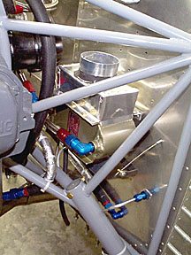
I am using stainless steel braided -6 hose for the fuel lines forward of the firewall. The
hose and AN fittings were procured at a local speed shop. The hoses are fairly easy to
assemble once you learn how to scowl properly at the fittings (liberal lubing of the
fittings with STP oil treatment really helps). I will have them pressure tested before
final fitting.
12/17/98; 2.0 hrs; fabricated hoses; mounted oil and fuel pressure
senders.
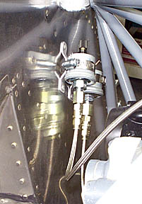
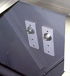
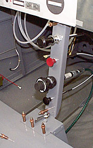
Senders for the RMI uMonitor (fuel and oil pressure) were mounted to the
firewall and connected to the engine with -3 stainless braided hose. Senders should not be
attached directly to engine because vibration can cause the fittings to break. Brackets
were fabricated from scrap, riveted to the firewall, and hose clamps secure senders.
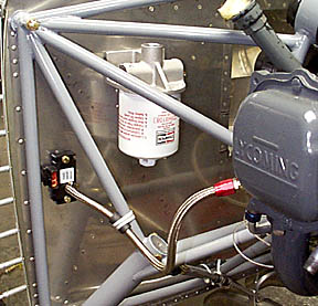
12/18/98; 2.0 hrs; fabricated hoses; mounted remote oil filter adapter and
manifold pressure sender. MAP sensor is GM part. Stainless -4 hose is a perfect fit on the
hose barb of the sensor.
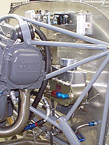
The oil filter adapter is a Moroso racing
unit for Ford filters (about $35.00). It is a perfect match for the Champion 48108
aviation filter. Filter will be plumbed in series with the oil cooler. The 48108 has a
bypass valve in case the filter clogs; Otherwise, it is identical to the popular 48110.
Update: The filter mount was removed from the plane after
just a few hours of flight due to consistent oil leaks. I
think the mount I have must be a porous casting since everything was done to insure the
fittings were oil tight. Oil continued to ooze from the mount so the casting apparently is
faulty. The mount hasn't been replaced since we have been too busy flying 399SB.
The original screen was put back in the engine and we now change oil on 25 hour intervals.
Reinforcements (1.5" x 4.0" x .125" scrap from the kit)
were riveted to the aft side of the firewall to distribute the weight of the oil filter
and adapter.
12/22/98; 4.0 hrs; relocated pressure sensors to clear area for
firewall-mounted oil cooler; installed fire sleeve on fuel lines; mounted master and
starter contactors; general messing around with engine stuff...
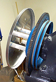
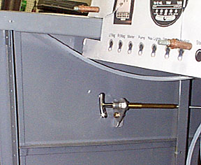
Since it will be several weeks before the prop arrives, this fixture was
fabricated to locate the spinner rear bulkhead so cowl work can proceed. It consist of
four 3/4" PVC pipes cut precisely to 2.25" to simulate the prop extension.
Hardware store 3/8" bolts hold the entire works together.
Be sure you mount the ring gear before installing the PVC spacers.
12/26/98; 0.5 hrs; mounted voltage regulator (VR166, standard issue early
70's Ford).
12/27/98; 3.5 hrs; installing oil cooler.
12/28/98; 3.0 hrs; completed installation of oil cooler.
The cooler is the Positech available from Van's. I am using the model
usually sold for the O-360.
A plenum to direct air into the cooler was fabricated from scrap sheet
stock. The flange on top of the plenum is sized for a 3" scat tube which will dump
air from the rear of the baffle. Pro-seal (slightly thinned with MEK so it could be
applied with a stiff-bristle brush) was used to seal the joints in the box and around the
flange.
Also note the flap at the bottom of the cooler. This is attached to a
push-pull control in the cabin so the air flow can be attenuated if oil temps are running
too low.
 The oil cooler flap control was procured from the aviation
department of a local auto parts store. It is a twist-lock design; This type of
control can be used for cabin heat and other ventilation applications......cheap and
readily available. The oil cooler flap control was procured from the aviation
department of a local auto parts store. It is a twist-lock design; This type of
control can be used for cabin heat and other ventilation applications......cheap and
readily available.
Notice the paper instruments....they cost considerably less than the
instruments you get form an avionics store....
12/29/98; 2.5 hrs; installing throttle, mixture, carb, and trim cable into
cabin console.
12/30/98; 1.0 hrs; hooked up throttle and mixture cables to carb.
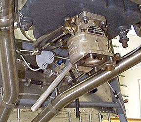
This photo shows the bracket that was fabricated to mount the mixture
cable to the Van's carb bracket.
Also visible is the crankcase vent tube between the exhaust stacks.
1/1/99; 5.0 hrs; completed installation of oil filter adapter; installed
cabin vent hoses; installed cabin heat cable; riveted caps on wing bulkhead.
1/12/99; 0.5 hrs; installed Robbins Wings 9" cabin heat muff.
1/18/99; 1.5 hrs; working on carb air box. Be sure you carefully
check the dimension when cutting the airbox to length; The instructions are confusing. The
correct length is shown on the sketch. Also, drill a drainage hole in the botttom of the
box.
Back to Firewall Forward, page one
Forward to firewall Forward, page three
Back to Finish Kit
Back to RV6 Home Page
Please submit all questions and comments to sbuc@hiwaay.net
|