The RV Journal Installing (and flying) the Lift Reserve Indicator
page one; installation of the LRI
|
 |
|||
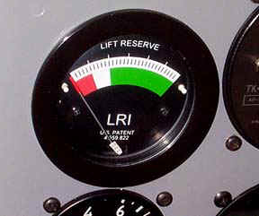
It is distressing how many pilots meet their demise due to stall/spin accidents. Even though one of the first things drilled into our head during primary flight training is "Don't get too slow!", pilots continue to find ways to prove that airplanes just won't remain levitated if the airspeed is allowed to decay below a certain point. Many of these pilots are high-time pilots; what is going on here? Are airplanes so hard to control that even accomplished aviators can't prevent deadly stall accidents? Unlikely. What is more likely is that complacency or inattention gets the best of many of the statistics. Another contributing factor may be the "mystical" relationship between stall speed and angle of attack. Get a hangar session started about the characteristics of angle of attack and you will be presented with wildly varying versions of what AOA is and how it impacts flight maneuvers. Military and airline pilots are accustomed to seeing an AOA indicator, but the average GA pilot has never seen a panel with an AOA indicator. If the military and most airlines think AOA is an important part of airmanship, why are GA pilots not using AOA indicators? Probably because the planes we trained in didn't have the instrument and for most of us, angle of attack was just a concept covered on a couple of exam questions. There have been a handful of AOA indicators on the GA and experimental market for many years. The sophistication of these units varies from simple analog indicators to fancy digital things that verbalize spoken commands. The price of these systems has been near $1000 and up, so many pilots have elected to leave the AOA indicator off their panels. One of the AOA systems that has been around the longest is the Lift Reserve Indicator. This unit was developed in the 1970's and has been offered in a couple of different variations since then. There is considerable controversy over just what the LRI actually measures and how it operates, but when the price of the analog unit was recently reduced substantially, it got my attention. Since the panel of 399SB is rather unconventional, I had included a small backup airspeed indicator. However, the AI was never used since I rely on the RMI uEncoder for pitot info, so I decided to replace the AI with the LRI since it could also serve as a backup airspeed indicator. The decision was easier since the LRI would fit in the same space as the little AI and was in the pilot's angle of vision. What is it?: Lift Reserve Indicator
If you want detailed information on how the LRI was developed and the way it operates, (and just what is Lift Reserve, anyway?) check out the company website for many articles on the subject. The unit mounts in a 2 5/8" hole or can be ordered for mounting on the top of the glareshield. The indicator is driven by a probe that is mounted on the underside of a wing.
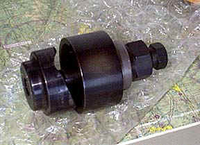
Since the airspeed indicator I was replacing mounted in a 2 1/8" hole, the hole needed to be enlarged. Al Mojzisik, co-patent holder and a distributor of the LRI, loaned me a Greenlee punch so the hole could be easily enlarged.
Here the punch is attached to the panel. As the large nut is turned, the cutter on the back of the panel is pulled through the panel stock. The resulting hole only needs minor touch-up before the gauge is installed.
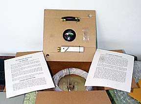
The LRI arrived securely packaged as shown. All tubing and fittings are supplied along with good instructions, and the estimated installation time is 4-12 hours. The unit can be installed on a certificated aircraft with only a 337 required if the heated probe is installed. I installed the unheated version since I don't fly in icing conditions.
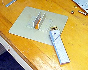
The probe included in the kit has two holes in the lower end, one pointing forward, the other facing downward. The probe is designed to be installed in the supplied plate which can double as an inspection cover.
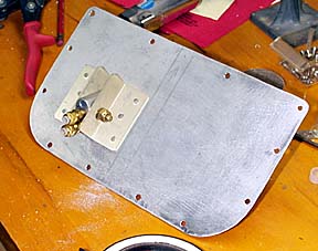
Since the inspection cover on the RV-6 is larger than the supplied plate, I fabricated a new cover out of heavier stock, removed the angles from the standard plate, and reattached them to the new cover.
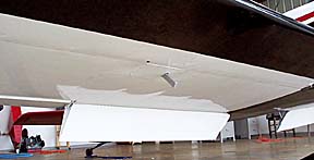
The probe is mounted at a 50 degree angle to the cover. This angle is easily adjusted per flight testing to properly calibrate the instrument.
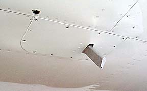
The installed probe is not too obtrusive, but not doubt it will prompt some questions as to "what is that thang?". I will probably reply that "it is the handle you use when carrying the wing panel.....".
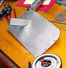
This photo gives a better idea of the overall size of the probe.
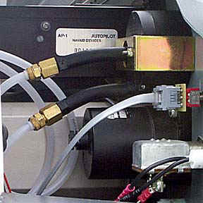
No doubt the biggest hassle of the installation is getting two small nylon tubes from the probe to the instrument. This would be very easy during construction of the plane, but is more involved in a completed aircraft, especially an RV which only has one inspection cover per wing. I was able to snake the tubing through the conduit I had previously installed in the wing, but it was an, ah, interesting task! The only connections required behind the panel are the two fittings at the indicator since no electrical power is required for the unheated version.
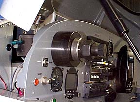
The LRI looks right at home in the admittedly unconventional panel of 399SB. Total installation time was about seven hours.
Forward to page two; Flying with the LRI
Return to The RV Journal front page
Please submit all questions and comments to sbuc@hiwaay.net
|
Getting Ready to Build Building the Tail Building the Wings The Finish Kit
|
|