The RV Journal Cold Weather Updates |
 |
|||
It's funny how you notice things in the winter that went unnoticed in warmer weather. Such as.........where is all that cold air coming from!? Here is a collection of updates I made to 399SB after winter arrived in Alabama.
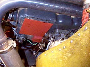
Even though genuine snowbirds don't think north Alabama has a real winter, we can often have a stretch of weather with temps well below freezing. I really don't like to start an aircraft engine when the engine has chilled down below the freezing mark. The oil is thick, various metals don't warm up at the same rate, and metal-to-metal contact can easily occur which results in accelerated wear to ex$pen$ive engine parts. After some research, I decided to install an oil sump heater since I have access to 110v in the hangar. I wanted a system that could stay connected all the time so the plane could be safely started at any time with no advance notice. A Reiff HotPadd was installed and I have been pleased with the operation of this simple system. (Be sure you read the Updates for this installation)
The HotPadd is glued to the bottom of the oil sump with silicone adhesive which is included with the heater. The cube you see at the rear of the heater is a thermostat which prevents the pad from exceeding 150F degrees. This is to avoid potential problems with cooking the oil. Reiff states that the pad should be able to maintain the engine temp 30-40F degrees above ambient temperature and that is what I have observed. The oil gets warmed even more (typically 80-100F degrees above ambient), and the heat migrates upward into the entire engine.
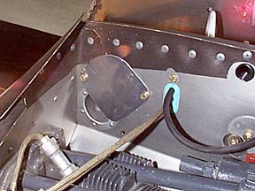
After pondering the best method for getting power to the heater, I decided to extend the power cord into the upper engine bay and out to the front of the engine so I could reach the plug through one of the cowl air intakes. A three-hole insulator (comes with a six cylinder mag harness) provided a neat way to penetrate the baffle.
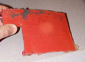
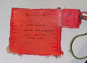
Adel clamps were used to keep the cord out of mischief and I cut some soft foam blocks to plug the air intakes while the heater was in operation. This is a really easy and relatively inexpensive ($119.00) method to keep the expensive stuff ready to go flying at a moment's notice. Pilots in colder climes may wish to add the cylinder heaters (HotBandds) that Reif offers, especially if the plane is banished to a drafty hangar (or no hangar at all!). Update, 12/6/01; The instructions state that all paint should be removed from the area on the sump where the heater is to be installed. I had used a combination of lacquer thinner and a wire brush in a drill to remove the paint, and all that remained was a very small area that stubbornly remained in spite of the solvent and brush. When the old heater was removed from the sump, it was still firmly attached by the adhesive and there was no evidence that the pad had detached from the sump prior to the removal of the heater.
Here is the back of the heater as it appeared when removed from the engine
sump. As you can tell, there are only trace amounts of gray paint on the pad, and these
are the only areas where paint remained on the sump where the glue was applied.
According to Reiff, this was sufficient to deem the installation to be improper and for them to refuse full warranty payment. Their claim is that this is sufficient paint to prevent the pad from properly transferring heat to the sump which caused overheating of the pad and failure. I was unable to get the indicated areas to appear in the photo, but according to Reiff, there was discoloration which indicated damage due to overheating.
Obviously, this development was a disappointment since I have personally convinced two hangar mates to buy Reiff products and no doubt several (many?) others have been sold as a result of this web site. I now no longer recommend this product due to the following reasons: 1) The heater is apparently intolerant to anything other than a perfect installation. In my opinion, if this is truly the case, this fragility is unacceptable for an item that is attached semi-permanently to an engine. 2) I am disappointed in the warranty service extended by Reiff Products. All the blame for the heater failure was placed on the installation. A "goodwill" credit for half the cost of the new unit was made, but a much more satisfactory show of goodwill would have been to replace the unit at no charge and at least acknowledge that there may have been a problem with the heater. 3) According to info on the Reiff website, the failure I experienced apparently is not an isolated case. Reiff has recently introduced a new HotStrip heater which reportedly is not susceptible to the type of failure I supposedly incurred. Interesting..... I still think a sump heater is a good idea. It is with regret that I can no longer recommend the HotPadd, and I suggest potential purchasers of Reiff products be aware of possible lack of full cooperation from Reiff when warranty claims arise. Update, 1/14/2005; The replacement HotPadd is now in its fourth winter and is still working perfectly. I usually begin using the heater in December and it runs continuously until late March. I recently had reason to pull a cylinder to repair some sticky valves and took the opportunity to carefully look for signs of corrosion on lifters, cam lobes, and the cylinder barrel. I am happy to report that no signs of corrosion were visible on the components that I could see from the #4 cylinder bore. I realize using a sump heater on a continuous basis is controversial and not sanctioned by engine manufacturers, but I am hopeful that my technique will be satisfactory in the long run. I think the remote chance of corrosion is a valid tradeoff for keeping the engine warm and avoiding destructive cold starts. If my plane was parked on a windy ramp or in an uninsulated hangar in a really cold climate, I would not use the sump heater by itself on a continuous basis because of the possibility of having large temperature differences in the engine compartment, and the moisture issues that could raise. In my case, as soon as the plane is returned to the insulated hangar following a flight, the heater is plugged in, cowl openings are plugged, and a blanket is thrown over the cowl. The entire process is an attempt to maintain the engine above the dewpoint, much as would be the case in warm weather. At no time have I observed moisture on the oil dipstick or any abnormal discoloration of the oil. The cylinder temps are routinely at 90F when the plane is pulled out of the hangar on cold Saturday mornings. I make every effort to fly the plane at least once a week during the winter and use AeroShell W100 year-round. I think the heavy oil and frequent flying are the most important factors for inhibiting corrosion. It is a pleasure to hear the warm engine and battery working in concert on a chilly morning as the engine is brought to life. Update 12/19/09: The HotPadd is still going, going, going........ The rise above ambient temp seems to have slipped a little over the years, but the heater is still maintaining the oil temp near 90F degrees. The HotPadd has been used 24/7 for about four months/year for eight years so it has accumulated quite an impressive number of hours. I often hear suggestions for using a timer to turn on a sump heater Friday evening for a Saturday flight. I am convinced that leaving the heater running continuously is far better than cycling the engine temp up and down with a timer. The key to avoiding corrosion is to maintain the oil above the dewpoint of the air in the engine. Continuous heating should be be able to achieve this goal better than having the engine temp rising and falling through the dewpoint.
One thing you notice very quickly in the RV-6 once the cold weather arrives is that there is a lot of cold air finding its way under the seat! The culprit is the four inch hole in the side of the plane where the aileron pushrod transitions from the fuse to the wing. Even though this area is covered with the wing root fairing, air somehow gets sucked into the cabin area from the wing. Even if you don't feel much direct air movement, the seat area gets very cold in various, ah, well.... sensitive locations.
You can view the drawing here. (432K jpeg)
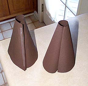
The material gets rolled into a cone and my resident seamstress agreed to sew the material using a double seam. After the seam is made, the cone is turned inside out so you get the results as shown. You may very well wish to use some other color than the lovely brown that I found in stock at WalMart. Just be sure the material is airtight and light weight.
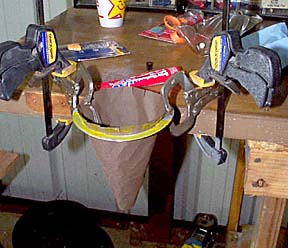
Next step is to fabricate rings from scrap .025" stock. Then you find the coldest available hangar (actually it wasn't too bad after we let the torpedo heaters work for a while) and attach the boots to the rings with contact cement.
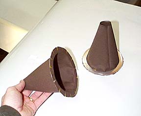
Here are the fabricated boots ready for installation.
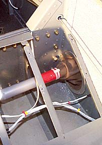
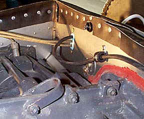
The best place to locate the boots is on the outside of the fuse in the wing root area before the wings are installed. Since I didn't want to remove the wings, and working in the confined wing root seemed like a lot of trouble, I decided to install them under the floorboards. This meant that the pushrods had to be disconnected at the control column so the boots could be slid down the pushrod into place. The ring was deformed slightly so it would pass through the lightening hole in the adjacent rib.
A couple of 1/8" holes were drilled, RTV sealant was gooped on the working surface of the rings, the boots were put into place, and pop rivets held them tight as the RTV cured. I put some duct tape around the small ends of the boots and further secured them with a couple of ty-wraps. Care was taken to insure that full control movement was possible with the boots installed. Do they work? Yeah boy! No longer does the seat chill down like a homesick Fridgidaire. There is still a little air leakage in the spar area but I think a few small strips of duct tape will cure those areas. All in all, this is a very worthwhile little project, especially if your plane is still in the workshop.
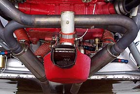
Another area that gets attention from some RV'ers is the heat muffs. I have found the single 9" Robbins muff to be a very well-crafted unit, but I need more heat! Per suggestions on the RV-List, I decided to stuff the muff. Supposedly this slows the air flow, increased surface area, and warms the air on the way to the cabin.
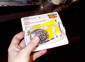
The last thing you want spraying out the heat vent is rusted metal. Stainless steel in the way to go and the closest source I could find was a local grocery store. Yep, what we want are stainless steel scouring pads. I also found some copper pads and almost went that route.
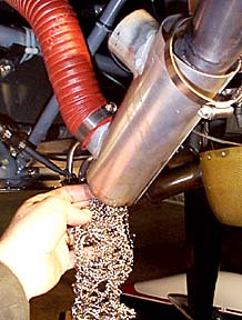
Only a few minutes were required to semi-disassemble the muffs so a pad could be stuffed into the muff. I "unraveled" the pad so it would fit loosely in the muff and not impede airflow. How does it work? Well...........only so so. I may add another muff and run the two muffs in series. I will keep you informed as to how that works out.
1/29/00; Update to the update: Ok, so the stainless scrubbies idea didn't work out too well. That just means we go to "Plan C". We skipped to plan "C" since "B" was to install a second muff. Plan "C" involves the fabrication of springs to be placed in the muff. If this doesn't do the trick then we will revisit "Plan B".
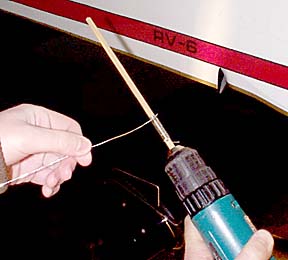
A 1/4" wood dowel was chucked into a drill, and 0.041" safety wire was wound onto the dowel. I made two "dowelfulls" of spring. Once the spring was removed from the dowel, I spread the coils apart slightly.
Each spring was anchored to the Robbins heat muff. I slightly mashed the coils on the side of the muff where the pipe-to-cover clearance was the closest. I ended up with about 24" of spring once the coils were spread out. Hmmmmm, this thing looks kinda like an electric heater coil....
After researching the heat problem with the aid of the RV-List archive, I decided to restrict the airflow into the muff in an effort to slow the air. This supposedly will allow the air time to warm more completely. Slightly closing the heat box won't accomplish the same effect since it is a "bleed" valve and will just dump excess warm air into the cowl area.
I had already fabricated the plate for use in the summer when I wanted to block any air from entering the heat system; This also allows maximum flow through the cylinders for engine cooling. Another hole was drilled in the rear baffle so the plate could be mounted in a halfway position. This should reduce the airflow through the heat muff. I will report the results as soon as further flight testing has commenced. Update to the Update to the Update; Well......the result of plan "C" has not been that impressive. There was very little additional heat generated by the springs, so I decided to revisit plan "B", which is to add another heat muff.
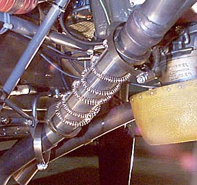
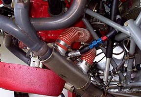
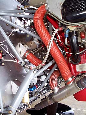
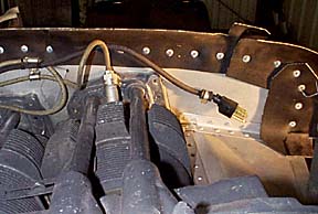
The muff on the left pipe is the additional muff. For some reason, the muff fits considerably closer to the cowl than the original muff, so close that there is occasionally contact with the cowl as evidenced by black marks on the muff.
The second muff was plumbed in series with the original muff.
The outlet of the first muff goes to the inlet of muff #2, and the outlet of the second muff goes to the firewall heater box. How does it work? Not bad! There is definitely more heat being transmitted by the system. I need to develop a diffuser of some sort at the heater box to direct air more evenly into the cabin. However, it appears the main obstacle to be overcome is preventing air intrusion into the cabin from the tail cone of the fuse. More work to come in this area.....
Return to The RV Journal front page
Please submit all questions and comments to sbuc@hiway.net
|
Getting Ready to Build Building the Tail Building the Wings The Finish Kit
|
|
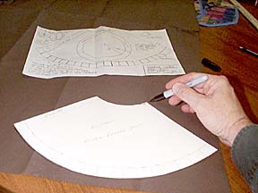 Fred Stucklin graciously sent me a drawing he developed for
fabricating boots around the pushrods so air can't migrate to the cabin. The drawing is
fullsize from which I cut a template for cutting material to form the boots. I went to
WalMart, purchased a duffel bag from the camping, ah, I mean aviation department,
and proceeded to cut the rubberized nylon material per the template.
Fred Stucklin graciously sent me a drawing he developed for
fabricating boots around the pushrods so air can't migrate to the cabin. The drawing is
fullsize from which I cut a template for cutting material to form the boots. I went to
WalMart, purchased a duffel bag from the camping, ah, I mean aviation department,
and proceeded to cut the rubberized nylon material per the template.