Panel Page
Firewall Forward
Interior Installation
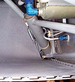
3/16/99; 6.5 hrs; working with fiberglassing upper gear intersection
fairings; installed platenuts for emp fairing.
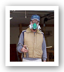
I am tired and totally disgusted after spending several hours in
fiberglass resin. This is the most despicable part of this project so far, far exceeding
proseal. There are no photos, because I was too sticky to even pick up the camera. Besides
that, I don't want to be reminded of fiberglass. Matter of fact, at this point I don't
even want to think. Good night.
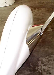
3/17/99; 4.0 hrs; installed emp fairing; glued airscoop to cowl.
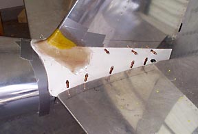
The fit of the emp fairing was pretty bad out of the box. However, after
the area at the root of the vert stab was cut away, the fit got better. Then, the whole
thing was reshaped with a heat gun. At that point, it fit quite nicely. I had to reglass
the area that had been removed earlier. Duct tape was applied to the stab to keep the
resin from sticking. The yellow stuff is Play-Doh that was used as a filler to build up
the shape of the stab.
I guess I am one of the lucky ones: I could actually use the emp fairing
that came with the kit!
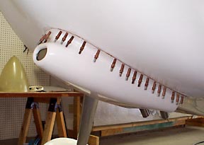
Scoop was bonded to cowl with a combination of resin and mat. Once again,
quite a bit of time was spent with the heat gun getting the flanges to behave properly.
Lots of clecoes hold the flanges in place as the resin kicks. All the holes will be
covered by glass cloth and filler.
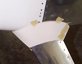
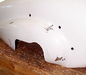
3/22/99; 6.75 hrs; fabricating aluminum gear intersection fairings.
I hate fiberglass!! I decided to try fabricating some aluminum fairings
before resorting to the fiberglass.
A paper pattern was cut out and taped into place. Considerable trimming
was necessary to get the proper profile.
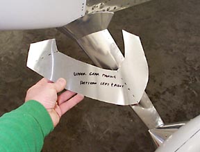
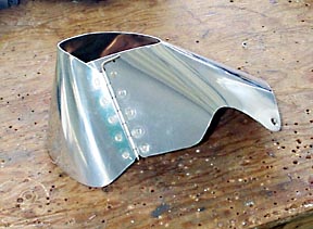
Here is what the pattern ended up looking like.
Fairing is fastened together with a countersunk #8 screw and platenut.
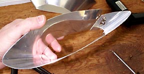
Here is how the upper fairings are secured in place (1/27/00)
"Ears" were riveted to the inside of the fairings and safety
wire was attached to the ears and to a spring. The spring is attached to a hook fabricated
from stainless welding rod.
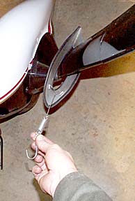
This is looking down at the gear leg. You can see the hook placed over the
gear leg brace. The wire is adjusted so the spring has moderate tension.
Hmmmmmmm....not bad! It only took two attempts to get to this point.
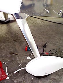
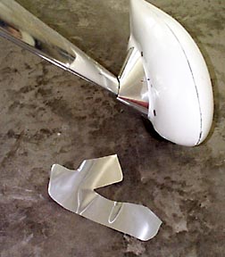
3/23/99; 4.0 hrs; completed lower gear fairings.
The bottom fairing is, well........ interesting. There are
several bends the sheet stock has to make. I used many pieces of poster board to make a
pattern. Matter of fact, I probably could have used it as a male mold for fiberglass
fairings. The pattern was cut apart just below the gear leg fairing and transferred to
aluminum.
I really didn't know if the aluminum would bend as necessary to form the
fairing. However, it did after much persuasion. This looks like it might actually work!
The fairing is fastened together with hinge material.
Now, to devise attachment hardware....
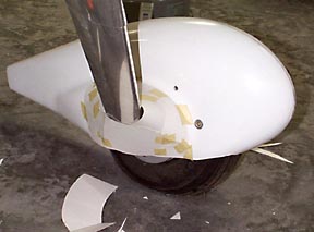
The two rear attachments are simply platenuts mounted on the wheelpant.
The forward attachments are 0.5" x 2.0" strips that are riveted to the inside of
the pant and carry a platenut on the outside.
The fairing has to split so it can be wrapped around the gear leg. A hinge
on the inside is used to fasten the fairing together.
As you can see by the pattern on the floor, the shape of the fairing is
complex; However, it will wrap as shown without any compound curves.
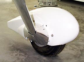
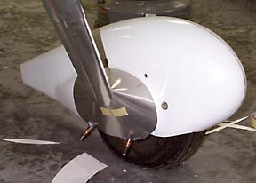
Here is the finished part. While not quite as detailed as a fiberglass
fairing, I can now build one in a couple of hours! The mounting is very rigid and the
fairing follows the contours of the wheelpant very nicely.
Not bad, eh? Rubber channel will be added to finish the intersection
between the two fairings.
Yes, making the aluminum fairings requires a lot of patience. However,
once they are finished......they are finished! I hate sanding fiberglass.
3/24/99; 2.75 hrs; More work on fairings; installed fire extinguisher; cut
and installed carpet padding.
Update 8/30/00; Now, after you have read all about the
metal fairings, click here to see what replaced them, and
resulted in more speed!
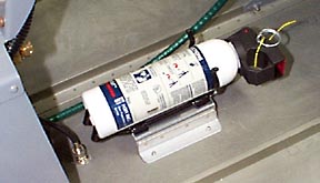
A platform was fabricated so the extinguisher will sit above the carpet
padding. It is located just forward of the fuel valve.
3/25/99; 2.0 hrs; working on air intake scoop.
After bonding the scoop to the cowl, lightweight filler was applied to the
joint. When cured, the filler and flange was sanded down smooth. Then a layer of glass
cloth was applied.
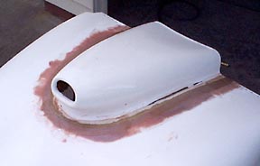
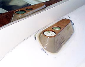
3/26/99; 1.5 hrs; made molds for nav lights.
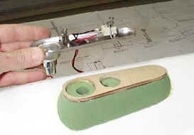
The AeroFlash nav/strobe light assemblies need to be mounted on the
wingtip so they are visible from above the plane. I used floral foam from the composite
aircraft department of Walmart to craft a mold that will be fiberglassed. These items are
available from Van's in case you aren't as cheap as I am (However, I am not sure if they
fit the AeroFlash units or not).
3/27/99; 5.5 hrs; fiberglassed nav light mounts; working on air intake
scoop.
I scooped out most of the foam after the layup had cured.
3/31/99; 5.25 hrs; working on emp fairings; completed elevator trim
installation; completed gear fairings.
The plans call for pop rivets to attach the trim cable attachment nut to
the trim cover. This means it would be very difficult to remove the cover. I
opted to use a couple of platenuts instead.
4/3/99; 9.0 hrs; completed airseal installation on baffles; installed air
ducts in top cowl; fabricated and installed cowl hardware; modified canopy release.
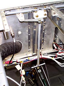
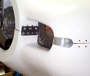
I decided to modify the canopy release so it could be reached easier. The
original tee handle was attached to the release bellcrank so I could reach it without
having to snake under the subpanel. The release is for maintenance purposes only since I
have no intention of jumping out of my plane...
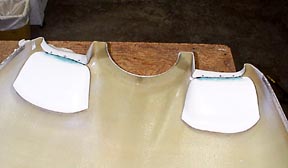
Here are those odd little fiberglass parts that you couldn't figure out
where to install. This are supposed to smooth the airflow into the baffles. I bonded them
to the intake lip with resin and mat, put in some flush pop rivets, then bonded them tot
he top of the cowl in the same manner. I should have waited about bonding them to the top
until the attachment at the spinner were completed because they pulled the front of the
cowl out of shape. They have to be trimmed a good bit to clear the baffles. I never did
figure out how to completely seal around the inboard end of the things with the airseal
fabric.
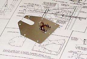
Here are the attachments at the front of the cowl. The plate on the
outside corner covers the slot where the hinge pin is installed and prevents the pin from
sliding out of the hinges.
I used three #8 flush screws and platenuts per side behind the spinner.
The platenuts are riveted to a plate that is in turn riveted to the cowl.
4/10/99; The shop has been cleaned out in preparation for wing attachment
and all that goes along with making this RV6 really look like an RV. Per careful and
deliberate guesstimation, I should be able to plug in both wings in my 24'x24' shop....
But right now......it is time to take off a few days and go to Sun-N-Fun!
Forward to Finish Kit, page six
Back to Finish Kit, page four
Back to RV6 Home Page
Please submit all questions and comments to sbuc@hiwaay.net
|