About Doppler DFs
Doppler Background
Doppler DF’s have become very popular in T-hunts and other "radio hunting" activities because they are fairly simple to construct and use, and they are quite effective. They are named for the "Doppler shift" principle of physics, which causes the frequency of a received signal to "shift" ( up or down ) from it’s "normal" frequency value, due to relative motion between the transmitter and receiver.
This principle is exploited in Doppler DFs by using a special antenna that generates an "artificial" Doppler shift on the received signal. This results in FM ( Doppler ) "modulation" of the received signal, consisting of an audio tone that has measurable qualities which vary depending on the signal direction. Doppler DFs measure these qualities to determine the direction.
Doppler Characteristics
Compared to other DF units, the primary virtue of Doppler DFs is their display speed... they have the ability to generate and update a DF display almost instantly, without any user activity. They excel when hunting signals of very brief duration, such as short "bursts" of interference. They also excel in mobile installations, because they allow continuous "homing" movement by the hunters, which accelerates the hunting activity. They are fairly simple devices, consisting mostly of low-technology audio circuits, and a few very simple RF circuits in the antenna. They became very popular in the 1970’s when economical RF PIN diodes became commercially available for antenna switching.
Doppler DFs are impressive, but they have some shortcomings and deficiencies. They employ ( low gain ) omnidirectional antennas that are vulnerable to reflections and multipath signals. For tracking weak signals, other types of DFs ( with antennas that exhibit gain ) are superior. Dopplers are also suitable mostly for signals at VHF frequencies and above, since the antennas become quite large at much lower frequencies. Dopplers can work with a variety of signal types, ( SSB, AM, etc. ) but the DF itself must employ an FM receiver. The antennas must generally be mounted at the highest point on a vehicle or a structure, to provide a clear, unobstructed view of the horizon in all directions. This ensures that reflections from nearby objects will be minimized.
Dopplers are not a panacea, and they are sometimes rendered useless in environments that are rich in reflected signals, especially if no "direct" signal path to the transmitter is visible from the receiving antenna. This includes downtown "civic center" areas, populated with large structures that have flat, orthogonal surfaces, and also ( in most cases ) "indoor" use. They perform best in "wide open" environments, where a clear view of the horizon is available. Therefore, altitude helps a lot… in some cases, an altitude change of only a few feet is required to achieve a clear horizon view, ( for example ) by driving to the top of a freeway overpass.
Doppler Accuracy
Most DF units ( including this one ) do not specify the bearing accuracy. This is done mostly because it is largely a fictitious and misleading number, which is ( moderately ) realistic only under ideal and/or "perfect" conditions. In actual practice, DF accuracy ( for all types of DF units ) is routinely "degraded" by external factors that are complete beyond the control of the DF equipment, and which cannot be overcome with "mere technology", no matter how sophisticated or impressive.
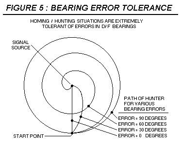
Fortunately, there are some basic geometric factors that make DF hunting very tolerant of errors... even very large errors. In situations where a DF is used to "home in" on a signal, tolerable errors can be very large, indeed. For example, if a hunter follows directions from a DF with an error of exactly 90 degrees, the D/F will lead the hunter "around" the signal source, ( endlessly ) in a perfect circle.

If the DF errors are greater than 90 degrees, the hunter will slowly "spiral out", and actually travel away from the source, but if the errors are anything less than 90 degrees, the D/F will direct the hunter to "spiral in", towards the source. Therefore, any display which can indicate the signal direction with an accuracy and resolution of less than 90 degrees error will ( eventually ) lead to success. If the errors are "reasonable" ( less than 30 degrees ) the hunter will merely travel along a somewhat "curved" path to reach the source, and may not even be aware that errors exist. Still, this behavior is based on the assumption that the signal is continuously available, and continuously observed.
For the benefit of those who insist on having a number, the PicoDopp DF has a mythical / legendary accuracy of perhaps 5 degrees, in ideal / perfect field conditions. ( best guess ) The accuracy observed during bench tests with an "artificial" Doppler signal is typically 1 to 2 degrees.
Doppler Principles
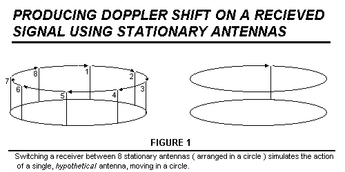
For illustration purposes, the following "example" Doppler DF uses 8 antennas, but most Doppler DFs actually employ only 4 antennas. In this example, eight vertical antennas are arranged in a circle, and the receiver is ( sequentially ) switched to each antenna, in turn. This simulates the action of a single "hypothetical" antenna, which moves in a circle. The resulting Doppler shift causes the received signal to be "Doppler modulated" with a sine wave, whose frequency is equal to the rotation frequency of the "hypothetical" antenna. ( Figure 1 )

To generate a significant amount of Doppler shift, ( about 500 Hertz at 144 MHz ) the antennas must be switched very fast... say, 4.2 KHz in this example. With eight antennas, sequentially switched at 4.2 KHz, the rotation rate of the hypothetical antenna is 4200 / 8 = (approx.) 525 Hz. If the antennas are arranged in a circle with a two foot diameter, this simulates the movement of a single antenna which is circling at a tangential speed of 3300 feet per second.... three times the speed of sound. The antenna switching is achieved with diodes, to deal with the high switching rates. A tangential speed of 3300 feet per second equals a speed of 500 wavelengths per second, at 144 MHz. ( hence 500 Hz of Doppler shift )
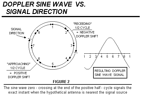
Audio filtering is required in the DF to remove any voice modulation, and to construct a Doppler sine wave with enough waveform quality to be useful. The filtered Doppler sine wave has two zero-crossing "events", which occur when the hypothetical antenna is "nearest to" the signal source, and "farthest from" the signal source. ( Figure 2 ) The "nearest to" zero crossing always occurs at the end of the positive half cycle, ( "falling edge" zero - crossing ) and it can be detected and used to signal the exact instant when the hypothetical antenna is closest to the transmitter signal.

The position of the hypothetical antenna can be tracked at every instant with a digital counter, which serves as the signal bearing counter. To guarantee "agreement" between the location of the hypothetical antenna, and the number in the bearing counter, the same counter is used to switch the antennas, and to track the signal bearing.
When a falling - edge zero crossing is detected, a trigger pulse is generated and used to trigger a data "latch" which takes a "snapshot" of the binary number in the bearing counter, at that exact instant. The resulting "snapshot" data is used to drive a display, consisting usually of a circle of LED’s which show the relative bearing to the signal source.

Doppler modulation is a form of frequency modulation, ( FM ) caused by relative motion between the transmitter and receiver. Because it is a form of frequency modulation, an FM receiver is required to detect it. The Doppler modulation in this unit consists of an audio frequency sine wave, so it will pass through the audio amplifiers of an FM receiver with very little trouble, and can be "sampled" ( by the D/F display unit ) directly at the external speaker jack of the radio.... no internal modifications of the radio are required.
Switching between 8 stationary antennas does not produce the same type of Doppler shift that would be produced by a single antenna, moving in a circle. If a single antenna could be constructed and rotated as described, the resulting Doppler modulation would truly be a sine wave signal, with very good waveform quality. Using 8 stationary antennas, the resulting Doppler modulation actually consists of a series of Doppler pulses, which must be carefully filtered to synthesize a ( reasonably ) pure Doppler sine wave. Voice modulation will ( usually ) be superimposed on the signal, so the filter must be very sharp to eliminate the undesired signals.
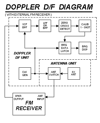
Virtually all Doppler D/Fs employ a switched capacitor filter, ( SCF ) followed by active lowpass or bandpass filters, to produce a Doppler sine wave with good waveform quality. The output of these filters is then fed to the input of a zero-crossing detector circuit. The output of the zero-crossing detector triggers an adjustable 1-shot, which allows the D/F to be calibrated to eliminate any residual bearing errors. The output of the calibration 1-shot is used to trigger the data latch, which drives the display.
Switched capacitor filters are very simple, but they have some very interesting qualities which make them ideal for this situation... they behaves like a resonant bandpass filter with multiple, harmonically-related resonances, and ( unlike most filters ) they require an external clock, to operate it. ( The SCF clock determines the center frequency of the filter. )
In Doppler D/Fs, the same clock which drives the antenna also drives the SCF, so the center frequency of the SCF is always guaranteed to EXACTLY equal the frequency of the Doppler pulses. This allows the filter to be designed with a VERY narrow bandwidth, usually much less than 1 Hertz, resulting in excellent voice audio rejection.
The PicoDopp does not employ lowpass or bandpass filters, but it does employ an SCF. The DC voltages that accumulate on the SCF capacitors are directly measured by the PicoDopp microcomputer, and these measurements are used to calculate the signal bearing, using trigonometry principles. This makes the microcomputer program very sophisticated and complex, but it also radically simplifies the circuit design and reduces costs.
For the benefit of those who may want still more theory regarding Doppler principles, the link below leads to another web page that describes details regarding the formation of Doppler pulses, and the significance of their measurable qualities :