This page provides several insights about Doppler pulses... Their amplitude, polarity, shape and duration, and how these quantities are affected by signal direction, antenna spacing, and receiver passband characteristics. It also provides some tips on the best methods for processing Doppler pulses, to extract the most meaningful information from them.
Doppler shift is a change, or "shift", of ( received ) signal frequency caused by relative motion between a signal source and a signal detector. The classic example of Doppler shift involves the change of acoustic pitch for a train whistle, ( or automobile horn ) as the train/auto passes by a stationary observer.
Positive ( "approaching" ) Doppler shift causes the received frequency to be greater than the "rest" frequency, and occurs whenever the source and detector are approaching each other. Negative ( "receeding" ) Doppler shift causes the received signal frequency to be lower than the "rest" frequency, and occurs whenever the source and detector are receeding from each other.
The amount of Doppler shift ( expressed in Hertz ) is proportional to the "rest" carrier frequency, and the relative velocity between the source and detector. If the velocity units are expressed in terms of (signal) "wavelengths per second", the resulting Doppler shift equates directly, because the two quantities are numerically equal : A transmitting and receiving antenna which are approaching each other at a rate of 500 "wavelengths per second" will cause +500 hertz of Doppler shift.
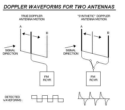
The rudiments of all Doppler D/Fís can be demonstrated with two antennas, as shown below. Switching between two stationary antennas simulates the action of a single, "hypothetical" antenna, which moves back and forth between the locations occupied by the stationary antennas.

If this hypothetical antenna could be moved with constant velocity, the resulting Doppler shift would be ( FM ) detected as a "square wave" signal... the positive half - cycles of the square wave would occur as the antenna "approaches" the signal source, and the negative half - cycles would occur as the antenna "receeds" from the signal source.
Switching between stationary antennas does not simulate constant velocity, but it does ( otherwise ) simulate antenna "motion". Because the hypothetical antenna "suddenly" moves between the two locations, the resulting Doppler shift is equally "sudden", resulting in Doppler "pulses". In this ( two antenna ) example, the Doppler pulses consist of alternating positive and negative pulse polarities : Positive pulses are produced by the antenna "nearest to" the signal source, and negative pulses are produced by the antenna "farthest from" the signal source.
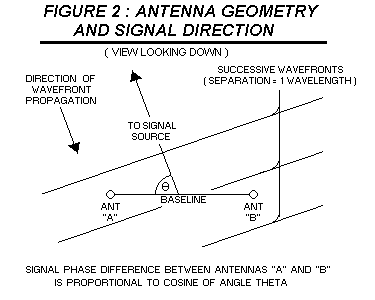
The Doppler pulses are caused by phase differences between the two antenna signals, as shown below. signals from antenna "B" will have a slight phase "delay" compared to signals from antenna "A". This is simply due to the fact that antenna "B" is farther from the signal source than antenna "A", so signals will require a slightly greater time to arrive at antenna "B". If antenna "A" is closer to the source by 1/4 wavelength, the phase difference will be 90 degrees.
If the input of an FM receiver is switched between the two antennas, the various resonant circuits in the receiverís R/F and I/F amplifiers will be forced to "adjust" to the change of RF signal phase, because these signals are derived from the RF signal. The total amount of phase change in the amplifiers is identical to the amount of phase change at the antennas. During this "re-adjustment" process, Doppler pulses are ( accidentally ) produced, as a "side effect".
The amount of phase shift between the two antennas is proportional to the COSINE of the angle formed ( 1 ) by the signal direction, and ( 2 ) the baseline which connects the two antennas. Minimum phase shift ( which equals zero degrees ) occurs for signals which approach the antenna pair from a "broadside" direction. Maximum phase shift occurs for signals approaching from a direction parallel to the antenna baseline, and is limited by the separation distance between the two antennas, expressed in wavelengths. ( 1 wavelength = 360 degrees )
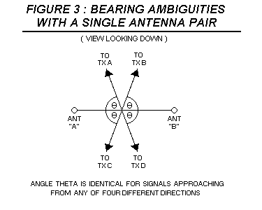
Doppler pulses of equal amplitude can be produced by signals approaching the antenna pair from any of four different directions, as shown below. ( The cosine for each of these 4 signal directions is identical ) If the Doppler pulse polarity can be determined, ( which requires a synchronous audio detector ) this reduces to two possible directions, because the antenna nearest to the signal source will produce positive Doppler pulses. Even with a synchronous detector, two possible signal directions exist, so more than two antennas are required to uniquely identify the signal direction.
The receiver passband characteristics ( determined primarily by filters in the I/F strip ) will control the actual shape, amplitude and duration of the Doppler pulse. It is difficult to predict these pulse quantities ( for a particular radio ) without a lot of substantial math, and without a lot of very detailed information about the specific filters in the I/F amplifier. It is much easier to simply measure the response with test equipment, but it takes some fairly expensive/sophisticated equipment to do it. In spite of this, some "generalizations" can be made.
I/F amplifiers with a narrow bandwidth will yield Doppler pulses of low amplitude, but long duration. Amplifiers with a wide bandwidth will yield Doppler pulses of high amplitude, but brief duration. In general, the maximum Doppler shift will occur near the leading edge of the pulse, and will gradually "taper off". In all cases, the TOTAL AREA of the Doppler pulse MUST be proportional to the RF signal phase shift that occurred when the antennas were switched, for reasons explained in greater detail below.
As a ( very crude ) "rule of thumb", the ( step - impuse ) "response time" for a narrow - bandwidth amplifier ( expressed in seconds ) equals the reciprical of the amplifier bandwidth, expressed in Hertz... an amplifier with a bandwidth of 1 KHz will require 1 millisecond to "stabilize" after the input signal is changed. An amplifier with a bandwidth of 10 KHz will only require 0.1 millisecond to achieve the same result.
If an FM receiver has an I/F bandwidth which is significantly wider than the linear detection range of the FM detector, ( FM detector "bandwidth" ) problems can occur... a portion of the Doppler pulse waveform will be "lost" by the FM detector... due to it's bandwidth limitations, it will not be able to "faithfully" detect the Doppler waveform.
DOPPLER PULSE ENERGY
Doppler modulation is a form of frequency modulation, ( FM ) caused by relative motion between the source and detector. Therefore, an FM reciever is required to detect it. The amplitude of ( FM - detected ) Doppler pulses is not as significant or important as the enclosed area of the pulses. ( the "energy" in the pulses ) This is true because the area enclosed by each pulse is directly proportional to the amount of phase shift that occurred when the antennas were switched, and ( therefore ) proportional to the cosine of the signal bearing.
The figure below shows a "rectangular" Doppler pulse, with a deviation amplitude of +500 Hertz, ( in the I/F amplifier, before FM detection ) and a duration of 0.5 milliseconds. It is possible to calculate the area enclosed in this pulse by multiplying its base ( 0.5 milliseconds ) by its height. ( 500 Hertz = 500 cycles / second ). This area will be expressed in units of phase shift because cyc/sec x sec = cyc. Note that one cycle = 360 degrees = 1 wavelength.
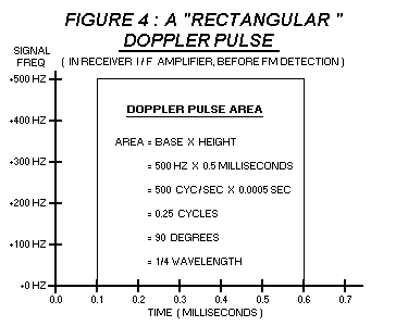
In this example, the area enclosed by the pulse equals ( 500 cyc / sec ) x ( 0.0005 sec ) = 0.25 cycles, which equals 90 degrees, or 1/4 wavelength. Therefore, the antenna which created this pulse is 1/4 wavelength closer to the signal source than the previous antenna. ( positive pulse polarity indicates it is closer to the source )
DOPPLER PULSE INTEGRATION
FM detectors are, by definition, "frequency to voltage" converters. Their behavior can be characterized with a single specification called the detector co-efficient, expressed in Volts per Hertz. ( input = hertz, output = volts, coefficient = output / input )
By multiplying the Doppler pulse area by the detector coefficient, it is possible to discover how the pulse area will be "expressed", ( what units of measure ) after it is FM - detected. Because the "pre - detection" pulse area is expressed in units of hertz - seconds, and the detector coefficient is expressed in volts / hertz, the "post - detection" pulse area will be expressed in units of ( volts ) x ( seconds), or "volt - seconds". Therefore, it is necessary to feed this ( FM - detected ) signal into a circuit which will translate a signal from "volt - seconds" into volts. If this is done, the resulting voltage will be proportional to the cosine of the signal angle.
An integrator circuit is suitable for this task. An integrator circuit produces an output voltage which is proportional to the "area" of an input pulse. The term "integration" actually comes from a branch of mathematics called calculus.... It is the name of the procedure that is used to calculate the area underneath a mathematical "curve", plotted on a graph. In electronics, the term "waveform" can be substituted for "curve", so circuits which perform this function are called integrators.
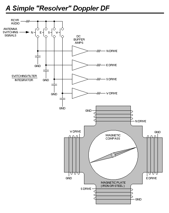
In Doppler D/Fs, the integration is actually performed by the switched capacitor filter. ( SCF ) A close examination of an SCF circuit will reveal that ( in one sense ) it is actually a set of individual RC - type integrator circuits, ( one for each antenna ) which are sequentially selected so that each antenna drives one specific integrator.
Just as an FM detector can be characterized with a single specification called the detector co-efficient, so too can an integrator be characterized with a specification called the integration co-efficient. For an integrator, the input signal is expressed in units of volt - seconds, and the output is expressed in volts, so the co-efficient of an integrator would be expressed as volts per volt - second, ( output / input ) or by canceling the common units, expressed simply as "1/seconds".
Multiplying the ( post - detection ) Doppler pulse area by the integration coefficient will yield the resulting ( integrator ) output voltage. This voltage ( in turn ) is proportional to the cosine of the signal direction, as observed by the antenna pair.
DOPPLER DATA PRESENTATION
By using two pairs of antennas, ( 4 antennas total ) and orienting the baselines of these two pairs to form a right angle, ( = orthogonal baselines ) then one antenna pair can be used to measure the cosine of the signal direction, and the other can be used to measure the sine of the signal direction.
Instead of performing actual measurements of these values, they can simply be compared against each other, to yield a "ratiometric" indication of signal direction. ( sine / cosine = tangent ) The circuit below shows perhaps the simplest example of how this can be done, using an ordinary magnetic compass as an indicator.
