The RV Journal Installing an APRS Tracker in N399SB
|
 |
|||
| One of the appeals of experimental aviation is our
freedom to incorporate new technology without the restrictions of FAA certification. This
has resulted in an explosion of exciting "glass" instrument panels and all sorts
of innovations forward of the firewall. Many of the innovations in certificated aviation
began in the experimental aircraft realm. There are other enthusiast communities with exciting technology and one of them is the Amateur Radio world. Hams have always demonstrated a willingness to expand the envelope of technology, and several years ago the introduction of digital radio produced the packet protocol. Packet radio is the transmission of "bundles" of data that can include all sorts of information. One application is the transmittal of GPS coordinates that are consequently transferred to the internet so the location of the transmitter can be tracked in real-time. This protocol is known as APRS (automatic position reporting system). Hams immediately began tracking their automobiles and other ground stations, and it wasn't long until hams who were also aviators began applying the technology to aerial installations. With the availability of tiny but full-featured transmitters that include the components necessary to encode GPS data streams, it is now possible for the aviator to embed a reliable APRS system in the airplane at a very reasonable cost. One vendor that offers APRS tracker devices is Byonics, located in Las Vegas, Nevada. Byonics offers several APRS solutions, from self-contained trackers to encoders that can be interfaced with handheld transceivers. The practical aspect of this technology is how the transmitter location, heading, speed and altitude can be overlaid real-time on a Google map or Google Earth. This allows someone to either follow the progress of the transmitter or to allow a review of the track after the fact. Only a moment's consideration will reveal the amazing possibilities for our aviation community. How many times have we embarked on a local sightseeing trip, or just a jaunt to "bore holes in the sky" with no particular route or destination in mind? These flights always have a happy conclusion....except for the extremely rare occasions when mechanical or other difficulties bring an unexpected end to the journey. How useful would it be to have a computer monitor within sight of loved ones or others who are aware of your flight so they could be kept informed of the locale of your flight, or in the unfortunate instance of an unplanned end of the flight, have a good idea of where to send those who are responsible for locating our plane? Even discounting the value for search and rescue, it would just be fun to pull up our flight upon returning home and seeing the track on our computer. This is made possible by the relaying of the tracker's packet transmission from our plane to ground-based digital repeaters and then on to internet servers which can be accessed by anyone. The GPS data accompanies the displayed track so flight conditions can be monitored or displayed. There are areas of the country where either the lack of repeaters or congestion caused by the popularity of APRS trackers make reliable tracking problematic. But it seems this is the exception rather than the rule and the APRS technology offers such potential that I deemed it practical and desirable for installation in the RV-6. Since APRS is part of the Amateur Radio service, a license is required to operate a tracker. Fortunately, only the lowest tier of license is needed, the Technician license, and no Morse code is tested during the exam. The exam consists of thirty-five multiple choice questions, and study guides with the complete 392-question pool are readily available. This means the license is attainable by anyone who is willing to exert a moderate amount of effort to learn the material presented on the exam.
The study guide I used is authored by Gordon West (ISBN 0-645053-45-2). The guide is written in a conversational style and reflects Mr. West's vast experience in the ham radio community. The questions and answers are worded exactly as they appear on the exam. I read the book one evening then began taking practice exams on-line. Once I got to where I could consistently score 90% or higher, I was ready for the exam. Passing grade is 75 and the exams are administered at scheduled times by local hams. The Technician license is valid for ten years and can be renewed without taking a new exam.
So...after having APRS brought to my attention by other RV pilots, I decided this technology was going to be installed in N399SB. There are basically two approaches to installation in our planes, one being to base the rig on a handheld transceiver. This requires, in addition to the GPS receiver, an encoder that can prepare the GPS data for transmission via the radio. Byonics offers the TinyTrak3 for this type of setup. This has the advantage of either using an existing radio or having a transceiver that can be used for other purposes than tracking. The disadvantage is dealing with several power and data cables that must be connected between all the devices and finding a place in the cabin for the equipment. The other approach is to use dedicated equipment for the APRS rig. The MicroTrak-300 is one of Byonic's solutions for this setup and allows the system to be embedded in the plane since it doesn't require pilot interaction, just the application of ship's power to operate. This is the approach I took since I didn't want to have the equipment in sight and didn't want to deal with cables every time I flew. (Update September 2008; The MicroTrak 300 in no longer available and has been superseded by the MicroTrak 8000FA which has a frequency-agile eight-watt transmitter. All other features are very similar to the MicroTrak 300. The only significant difference is the need for regulated 12vdc power for the MT-8000FA. Byonics has a nifty little regulated power supply that works very nicely in our applications.)
The MicroTrak-300 is a miniature two-meter transmitter with the necessary encoder to interface with a GPS receiver. All that is required is connection to the GPS, 12v power, and an antenna. The data and power connections can be via a DB9 connector on the device. Byonic offers the MicroTrak as either a kit or assembled and tested. Since the difference in price between the two options was only nine dollars, I went with the assembled version. The tracker ships in a plastic sleeve that can be trimmed for a perfect fit and allows you to see two LEDs that verify GPS data and transmission.
Here are a couple of Yahoo Groups that will be of interest to users of the MicroTrak: http://groups.yahoo.com/group/MicroTrak http://groups.yahoo.com/group/TinyTrak
A connector is shipped with the unit for a 9v battery (9-15vdc required) but since I intend to power the tracker from the avionics bus I soldered a jumper from the + power pad on the board to pin 9 of the DB9. This allows me to supply 12vdc through the DB9 instead of a separate lead. However, this method won't work if the DB9 is used to plug a GPS directly into the tracker. It works for me because of the custom harness I use for interfacing with the GPS and aircraft power. The MicroTrak also outputs 5vdc so a 5v GPS can be powered by the tracker. I am using a Garmin GPS35 that is already in the plane so the power output is not needed for my installation.
Here is the test lead I made for powering the unit during configuration. The supplied battery connector goes to pins 5 and 9, and pins 2 and 3 are connected on each DB9. However, 2 and 3 must be crossed so the cable functions as a null modem while the device is connected to the serial port of a computer. I also connected pins 5 so there would be a signal ground.
Several options exist for antennae for APRS applications. For airborne apps, the list is a little shorter due to obvious reasons. Some APRS pilots are using a simple J-pole antenna constructed from TV twin-lead. This is an effective option even when the antenna is mounted in a fiberglass wingtip and not oriented completely for the optimal vertical polarization. I elected to build a simple 1/4 wave whip and installed it on the bottom of N399SB.
The element is 1/8" stainless welding rod which is tightly inserted into the center conductor of a PL259 connector, then potted with JB Weld. Cutting the element to 19.45" will optimize it for the 144.390 MHz APRS frequency. Fine tuning could be accomplished with an SWR meter but I haven't found that to be necessary. The tracker can tolerate a mis-match far worse than this antenna would present.
The matching SO239 connector is attached to the inside of the belly of the plane via a 3"x3" doubler.
Software and manuals are downloaded from the Byonics site so the tracker can be
configured for installation. Here is a screenshot of the config setup showing the various
parameters that can be tweaked. Not all of them are necessary for our use, but the tracker
is a quite versatile little unit. A feature that is valuable for use in a vehicle with such a wide speed range as our RV's is SmartBeaconing. This is an algorithm that changes the frequency of position updates depending on the speed and direction of the vehicle. This triggers the occasional update when the plane is flying in a straight line, but more frequent updates when maneuvering. This results in a very smooth and accurate plotting of ground track on the Google maps.
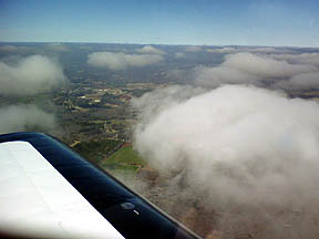
Well....time to fly this puppy! The day after my call sign appeared on the FCC database, the weather cleared sufficiently for a test flight. The following screen shots are from the aprs.fi website which interfaces APRS trackers with Google map products. The flight called for a departure to the NW from DCU, a climb above the scattered clouds to 3500' msl (2800' agl), a few maneuvers, then a return to DCU at a lower altitude to see how many beacons would appear on the website. Upon arrival at DCU, a touch-n-go was flown to check out the SmartBeaconing settings and low-altitude performance of the system.
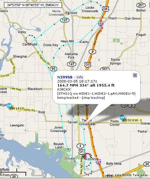
Here is the flight as it appeared in real-time on aprs.fi. Each red dot signifies the transmission of a beacon. You will notice how the SmarBeaconing algorithm decreases the interval between transmissions when the plane yaws in a turn. This creates a smooth rendition of the turn on the map. By clicking on a dot, a bubble appears with the data from that particular transmission. Not only is flight info displayed, but the path of the beacon as it was received by a digipeater and sent on to the internet gateway. The 1/4 antenna performed superbly. There are no repeaters in the immediate vicinity of Limestone county, but the little 300mw tracker was hitting a repeater either twenty miles to the south or one thirty miles east. During the turn at the west end of the flight, one beacon was received by a station in Nashville, nearly 100 miles to the north.
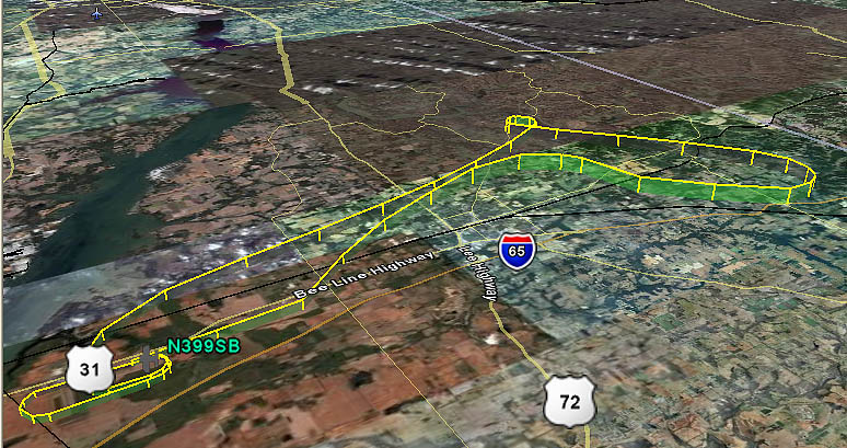
Below is a really intriguing version of the flight track. Aprs.fi has a feature that plots the track on Google Earth. You can see the relative altitude of the flight and where each beacon was transmitted. This would be of tremendous value if it was necessary to initiate a search and rescue operation.
If you interested in setting up a personal iGate, the process is inexpensive and interesting if you enjoy installing and tweaking free software. I installed an iGate in my office and it is interesting to watch how it ports APRS traffic to the internet. A personal iGate would be especially valuable for aviators who have no or very few iGates in their area. A couple of iGates can plug major holes in the APRS network.
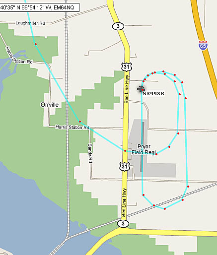
This screen shot show N399SB upon arrival back at DCU and the ensuing touch-n-go and lap around the pattern. The final beacon was only about 200' agl and was received by a repeater about ten miles south of the airport. Just a cursory look at APRS technology will reveal not only the entertainment value, but the very real contribution it could provide in the case of an off-airport landing. It will be interesting to see how available is coverage as we fly the system to various destinations. But even sporadic coverage would be better than none. APRS certainly does not replace the conventional safety aids such as flight following and ELT's, but it is a great example of how digital technology can be applied to aviation.
The MircroTrak has a feature in its config menu that bears further investigation. You can input a secondary configuration file that is activated by a switch external to the unit. The secondary config could include a universal distress icon and a message stating an inflight emergency. A phone number could even be included in the text. There are ham operators all over the world who have their stations set up to recognize this distress protocol and no doubt it would be only moments before local authorities would be aware of the seriousness of the situation. Hopefully we will never need to use this feature and APRS will just be a source of great interest and entertainment. The best collection of info about APRS aviation tracking I've seen is the APRS forum on the VansAirforce forum: Now.......to figure out how to do some sky-writing....
Update: The Micro-Trak 300 works like a charm in N399SB. The customary installation of
this little tracker has it hidden in some out-of-the-way corner of the plane and it is
very content to hide there and do its thing with no human intervention. Feed it power and
data and it just keeps pumping out the beacons.
Here is the little remote panel I fabbed out of scrap 3/4" aluminum angle: It carries a mini SPST switch (power for the tracker, may be eventually replaced with a SPDT so the tracker config can be changed for emergency beacon) and two LEDs, all from the local Radio Snack store. The red LED lights each time the tracker sends a beacon. The green LED blinks when the tracker is acquiring GPS data during bootup, and glows steadily when good data is being received from the GPS.
I decided to just cut the traces on the board between the resistors and the LED's. This is minimally invasive since all it would take to restore the onboard LEDs would be jumpers around the trace cuts. The photo below shows how I ran jumpers from the resistor pads to the DB9 so the external LEDs could receive their signals. I also added a ground wire so I wouldn't need to ground the external LEDs to the airframe. The red wire is how I supply ship's power through the DB9. A test rig on the bench proved the new setup works perfectly and the remote indicator panel will be attached to the bottom lip of the instrument panel next to the left side of the cabin.
While in hacking mode, I decided to go ahead and run a lead to the DB9 for triggering
an external amplifier. Byonics has a little 8 watt RF amp that I intend to add to the APRS
rig and it needs a signal to tell it when to power up. This signal comes off the same
trace that powers the red "transmit" LED on the board.
Return to The RV Journal front page
Please submit all questions and comments to sbuc@hiwaay.net
|
Getting Ready to Build Building the Tail Building the Wings The Finish Kit
|
|