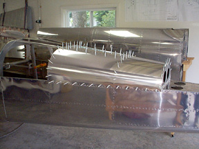
8/12/98; 4.25 hrs; drilled, deburred, countersunk, dimpled, trimmed and
clecoed aft top skin to fuse.
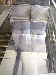
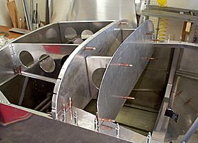
8/13/98; 2.0 hrs; fabricated and drilled baggage compartment floors, sides
to fuse; drilled baggage rear bulkhead.
8/14/98; 3.5 hrs; installed platenuts in baggage compartment.
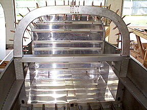
8/16/98; 3.5 hrs; completed baggage compartment; installed shoulder
harness cable brackets.
8/17/98; 3.0 hrs; installed control column; drilled and riveted seat
bottom skins.
8/18/98; 2.5 hrs; trimmed, drilled forward seat bottom skins. Man,
I hate installing platenuts!
8/19/98; 4.0 hrs; more trimming of seat skins; installing manual
flap system.
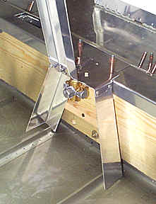
The flap handle was shortened so it would rest closer to the floor when
the flaps are retracted. This will also give more mechanical advantage to the system due
to the new angles of the actuator arms.
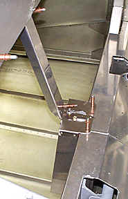
8/20/98; 2.25 hrs; flap actuator installation and fabrication.
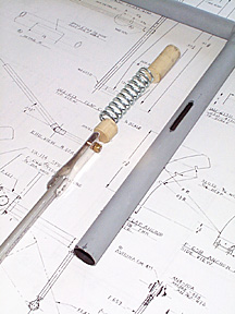
I cut the wood block into two parts. This made the release mechanism
function much more smoothly since the end of the spring couldn't catch on the end of the
slot.
Update 6/23/00: I have retrofitted electric flaps. The
manual flaps worked perfectly, but it seems I occassionally carry passengers that
feature....uh......wide bodies. Several times I have attempted to grab the flap
handle and found it obstructed by hips that were overhanging the passenger seat. To avoid
this issue, and to free up a little cabin space, I decided to install the electric flap
kit. The installation required about eighteen hours of hard effort in the confines of the
cabin, but the installation works as advertised.
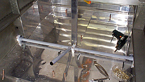
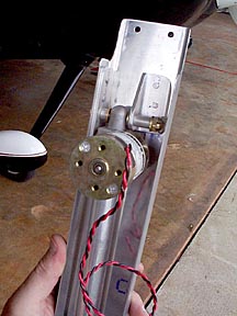
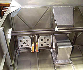
Here are the basic components of the system. I had RV-9A builder Randall
Eckstein modify the standard flap torque tube; the kit included new ends that are welded
to the tube after the arms are shortened. A completely welded tube is available, but I am
cheap.
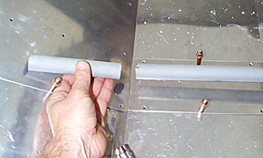
Those of us with tip-up canopies have to work around the latch rod. The
forward channel could go under the rod, but I found it easier to place it over the rod to
give more clearance for the motor. Two side covers are supplied to finish the installation
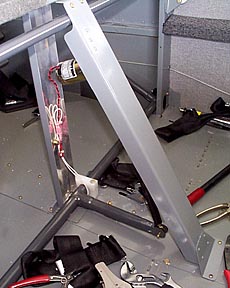
The motor attaches via a couple of brackets that are fabricated from
supplied angle and flat stock.
I set up the system so it is hot all the time. A fused line was run
directly from the battery side of the master contactor so the flaps could be activated
without turning on the master switch. This will be useful when assisting passengers into
the plane on the ramp.
Even though the manual flaps were very satisfactory, I am going to enjoy
the electric system. It has proven to be very reliable in the field, and I have some ideas
for utilizing the space opened up between the seats.
Update 7/14/00; There was still one thing lacking for 399SB
to be the compleat aeroplane.........cupholders! The electric flaps left an area between
the seats free for customization, and the following little project was the result.
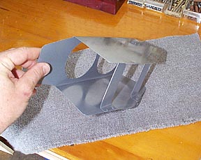
I made a pattern of what I wanted from posterboard, tranferred it to some
scrap stock, added a couple of pieces for support, and ended up with this contraption. It
drops snuggly into the space between the seats.
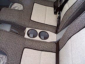
Another view. The fabric is a scrap left over from the cabin sidewalls.
The holder is painted with the same luxurious shade of Rustoleum Smoke Gray as the rest of
the cabin.
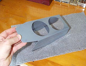
The finished product following covering with fabric. Weatherstrip cement
was used to attach the fabric, and the edging around the holes is automotive vacuum hose
slit with an Exacto knife.
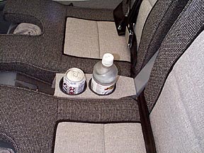
If the holes have a finished diameter of 2.875", they will
accommodate either cans or water bottles. The supports that were shown in the first couple
of photos serve as the "bottoms" of the holders.
8/21/98; 1.5 hrs; began construction of seat backs.
8/23/98; 3.5 hrs; completed seat backs and attached to fuse; finished seat
back reinforcement; fine-tuned flap actuator.
In order to maximize leg and head room, I am forgoing the adjustability of
the seat backs. Only one set of bottom hinges are located at the aft position, and I
am not using the adjustable seat back braces. Cushions will be used for very short
passengers.
8/28/98; 1.5 hrs; fabricating battery box.
8/29/98; 5.75 hrs; completed battery box; installed firewall recess box;
riveted upper firewall gussets; fabricated and riveted F-653 gussets to F-606 and F-607.
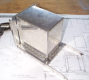
Here is the completed battery box assembly.
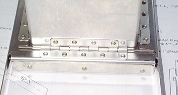
I used the suggestion in the Justice notes for securing the hinge pins. If
you look closely, you can see the right end of the rear pin is secured in a 1/8"
hole. The rear pin keeps the side pins from sliding out of their hinges. The battery box
can be easily opened without tools. Cool!
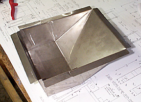
I purchased the flat, laser-cut stainless steel firewall recess thingy
from Van's. This is how it looks when it is bent into shape and ready for installation.
The recess is necessary if the engine has an oil filter or prop governor.
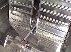
All the goodies in place around the firewall. I will have brakes on the
pilot side only.
8/31/98; 1.5 hrs; prepared forward deck components; began assembling
forward deck section.
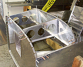
No, this is not the instrument panel. This is a bulkhead; the
panel will mount about six inches further aft.
Here is the cabin deck taking shape. Some degree of trimming and fussing
is required.
9/1/98; 2.75 hrs; completed trimming and drilling cabin decks; made first
trim and fitup of instrument panel.
Oh, by the way, I am building the tip-up canopy version.
9/3/98; 5.0 hrs; panel installation; fabricating center console; mounted
fuel valve.
Wood spacers are attached to the false spar to accurately locate the base
of the fuel valve mount. I have decided to use the control console between the valve and
the panel. I have to mount the manual elevator trim somewhere, and the console
will make a good place to locate the fuel gauges as well.
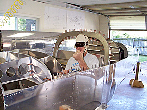
Ah yes....sitting in the project making airplane noises....
Forward to Fuse, page eight
Back to Fuse, page six
Back to RV6 Home Page
Please submit all questions and comments to sbuc@hiwaay.net
|