Tday, 90SS Buildup (Warning: slow load ahead - there are
lots of pictures)
(Click here for the Phase I parts list.) OR Click here : for phase II, the 496 Stroker OR Click here : for phase III
Click here for Caltracs Installation
|
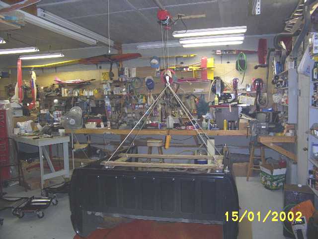
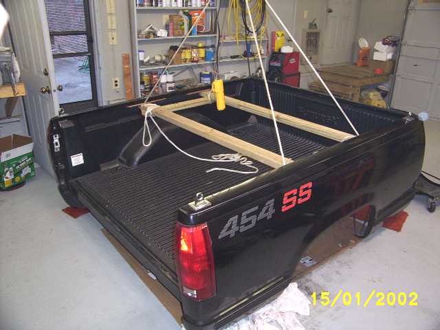
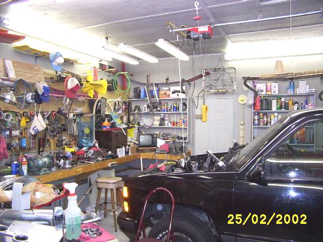
Removing the bed using an overhead electric winch and a 2x4 frame used to support the bed. |
|
A better picture of the method used to support the bed during removal. Note the small wooden blocks just under the lip of the bed. These were used to prevent denting the edge of the bed. |
|
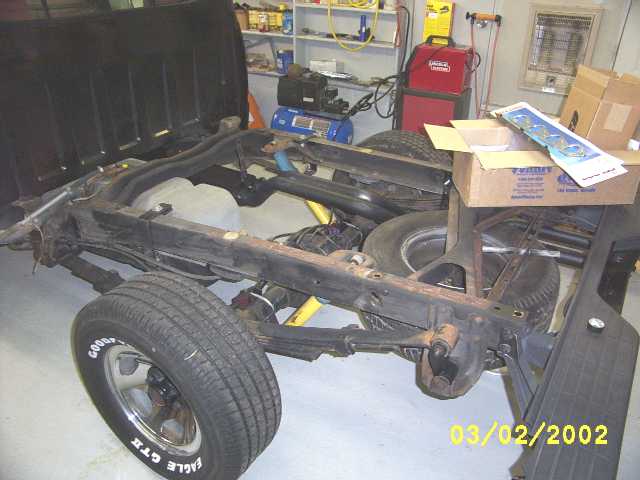
The frame as it looked after bed removal, and just prior to painting. Note how clean the floor is. |
|
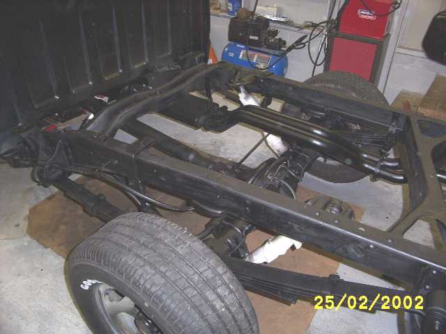
A little pressure washing, some wire brushing, and a little Satin Black Rustoleum and it looks like new. Note, the masking paper is still on the shocks. Note the over-spray on the floor. I guess I should have used a larger piece of cardboard J . |
|
A shot of the winch over the engine bay of the truck. This is how I lifted the intake, and cast iron heads. Those iron heads weigh 75 pounds each. The new Edelbrock Aluminum heads only weigh 39 lbs each. |
|
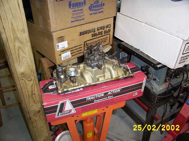
The old Edelbrock intake and stock throttle body assembly. Note the new heads are in the white boxes to the right of this picture. Also note the traction bars in the box under the intake --They DO NOT fit the truck. They are designed for axle over spring, not the reverse. I sen\td them back to Summit even though I had them more than 90 days. Summit only gave me a 90% credit because I had them too long. |
|
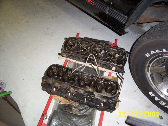
The old cast iron heads. H-e-a-v-y. 75 lbs each. The new heads only weigh 39 lbs each. |
|
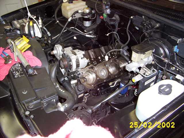
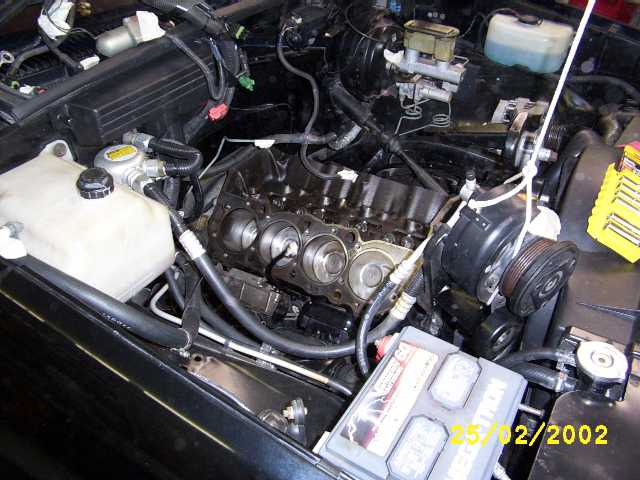
Driver side view of the engine after head removal. I spent a few hours cleaning off the pistons and block surface. The pistons were really carbon coated! WD-40, Carb Cleaner, and a Cup style brass brush on a drill. Note the large pipe on the radiator support. That 2' pipe was slipped over the 1/2" drive ratchet handle and used as extra leverage to break the head bolts loose. (Unknown to me at the time I took these pictures, but 2 of the main bearings and 4 rod bearings were on the verge of total failure due to an oil starvation problem.) |
|
Passenger side view. |
|
|
|
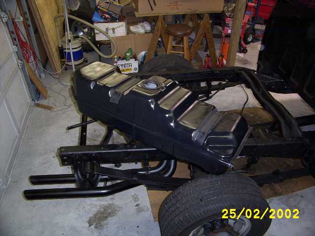
The gas tank was removed and a couple of 3/8" fittings were welded into the bottom rear of the tank. The new fuel lines will connect there. Notice the paint job on the tank. No one will ever be able to see it, but at least I will know it was done. |
|
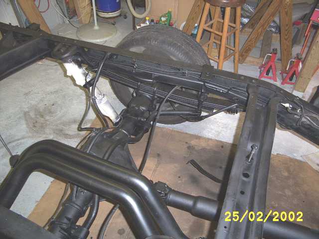
A view of the fuel tank end. This is where the supply and the return will eventually go. For now I have a temporary line connected that I used for testing the fuel pump and filter. This will be used as the return line. I drilled holes and welded in two 3/8" bungs on the end of the tank. Then I leaded/soldered the area around the weld on the outside, and coated the tank with fuel tank sealer on the inside where the 3/8" fittings were welded in. A lot of work, but No leaks! |
|
A shot showing the Helwig Rear Swaybar mounting location. The helwig swaybar only costs $123, but is of poor quality. It has poor quality fittings and a very poor quality paint job. I had to sand and repaint the swaybar before I installed it. However, it seems to work just fine. I've had it on the truck since 99. |
|
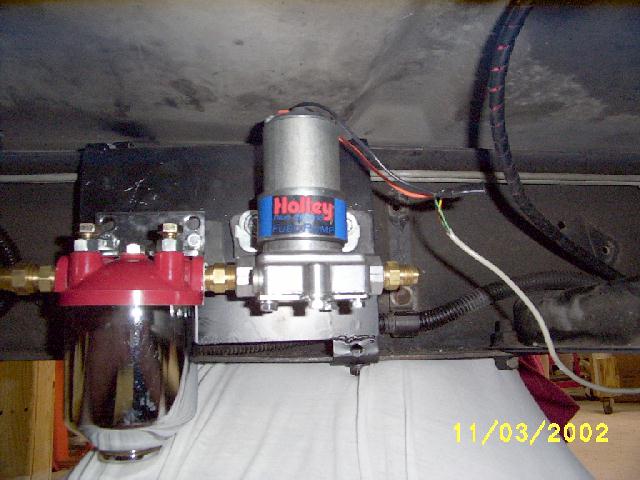
The Holley "Blue" fuel pump and Summit Fuel filter. Note: the Summit filter quality appears adequate, but the filter leaked when I first hooked it up. It took new copper washers, and silicone sealer to stop the leak from the top of the filter. I DO NOT recommend this filter. When it's time to replace the filter, I will replace the entire filter assembly. The Holley pump is NOISY. Next time I would probably try a Mallory instead. Note the temporary wiring at the right of the picture. This was for testing the pump. I ran 8 gallons of gasoline through the pump during the test. 3 times! BTW, the white surface below the pump is me. It's my T-Shirt. I was llying on my back stuck under the truck while I took the picture. Note the firm contact between the frame and my body. I'm getting thicker in my old age J The pump and filter are mounted on a 12 x 6 " metal plate that is bolted to the inside of the truck frame. I have the filter and pump mounted on 1/4" thick rubber to help isolate vibration and noise, but it is still noisy. |
|
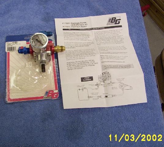
Barry Grant "Bypass" fuel pressure regulator, # 171021, Cost $60 at the local speed shop. I bought it to replace the dead-head type Hollley regulator that came with the Holley "Blue" pump. The Holley regulator is of poor quality. The Barry Grant regulator looks and feels to be excellent quality. |
|
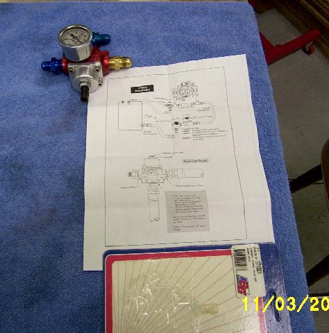
Barry Grant "Bypass" fuel pressure regulator, # 171021, I have inserted some fittings in the three 3/8" ports, and a fuel pressure guage in the 1/8" port. The instructions are are also displayed. These instructions are much better than the Holley instructions that came with the Holley pump and regulator. |
|
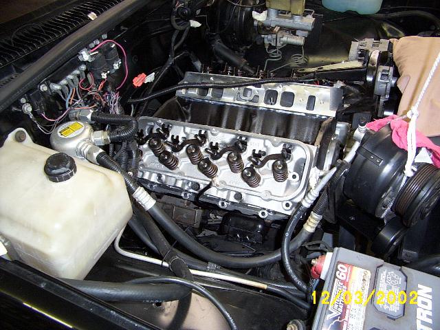
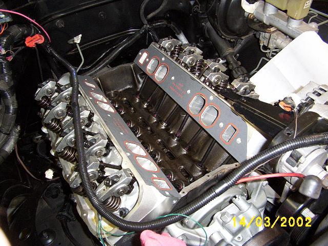
The Edelbrock Aluminum heads, just after placing them on the block. Installing the headbolts and torqueing them down was a major task. I did it in 5 steps. First I installed all the bolts (with thread sealer) and snug them up. Then torqued to 20 ftlbs, then torqued to 40 ftlbs then torqued to 65 ftlbs then the final torque to 75 ftlbs on all except the very short bolts , (the short bolts torque to 65). That's 32 bolts times 5. Can you say tiresome! BTW, I used the Edelbrock recommended Felpro 1017-1 head gaskets. |
|
Heads with the Crane Roller Rockers, Comp Cams 3/8" Magnum pushrods and Mr. Gasket Ultraseal #5827 intake gaskets installed. Ready for the intake. Edelbrock Gask-a-cinch was used between the intake gasket and the heads. (Weeks later, when I had to tear this engine down to rebuild it, the gaska-chich made it difficult to get the intake loose. However, it sealed well and I had no leaks.) |
|
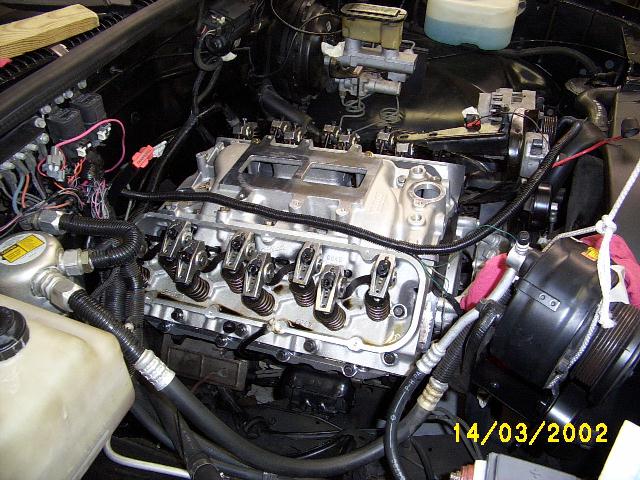
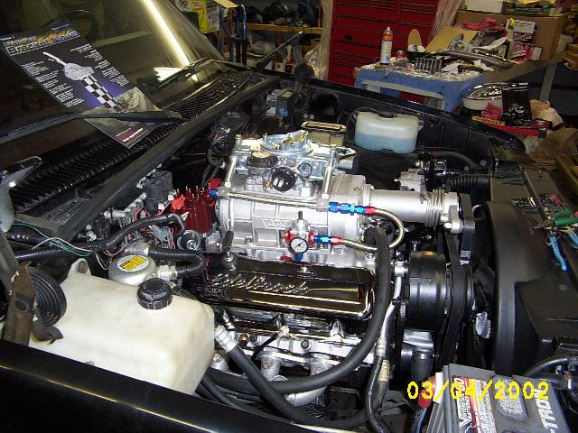
The Weiand Superchager intake is installed. I used Edelbrock Gask-a-cinch on the intake gasket, and all mating surfaces. Seems to work well. Looks and smells a lot like CPVC pipe glue. Seems to dry to a sticky stuff much like the sticky stuff on the back of 3M Postit Notes Talk about unrestricted airflow…you can peek through the top of the intake and see all the way into the heads and see the valves. Mmm mmm good. . Note: The altenator accessory bracket that goes to the intake will not fit the new intake. Some fabrication will be required…. Time for the Sawsall, welder, and the angle grinder J |
|
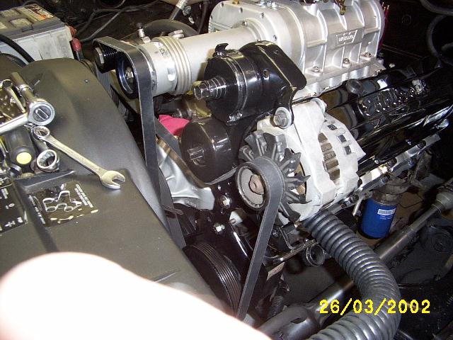
Talk about predicting the future! The previous picture only hints at the problems to come. The alternator bracket and the A/C compressor both interferred with the supercharger snout. I spent the entire weekend pondering, cutting, drilling, and welding to re-do all the accessory brackets so that the drive belts, and accessory bracketry would clear each other. For the A/C all I had to do was rotate the cast bracket back a few inches and redrill the bracket and mount it to the head. I also had to modify(extend) the little bracket that attached the compressor to the corner of the intake. For the alternator, belt tensioner and power steering pump bracket, it became a major operation. I had to cut the bracket in-two between the power steering pump and the alternator. This left the PS pump in it's stock location, but needing an inner brace. I then cut the inner leg off of the alternator bracket so that I could rotate the alternator and belt tensioner bracket up and away from the supercharger. (the right outer leg remained and became the pivot point) Basically this stood the bracket straight up. I then fabricated new Z bracing for the PS pump and the Alternator out of 3/16" X 1" steel. (Easier said than done! This required much time to be spent with the 3 lb hammer, and big vise.). I used 1/8" X 1" steel to brace the top right side of the alternator back to the head where the original alternator rod-shaped brace had been attached. In this picture you can also see the routing of the flexible radiator hose under the alternator. The hose is 30" X 1-1/2" and cost $10 from Advance Auto. It required a Gates 1-1/2" to 1-1/4" adapter fit the radiator inlet. |
|
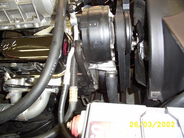
I rotated the A/C bracket down about 2 inches and redrilled it. In this picture you can just make out the new bolt (copper colored because of the antisieze) just under the A/C compressor. I had to rotate the compressor down out of the way of the Supercharger snout. |
|
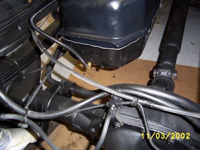
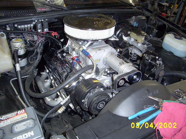
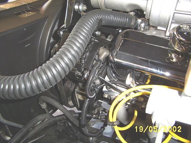
This is a pic taken from the passenger side showing the fuel line routing and the PCV line routing. In this picture you can see the Barry Grant bypass regulator and fuel pressure guage. The supply and return fuel lines are not yet connected. |
|
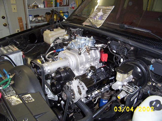
Driver's side view. In this pic you can see the throttle linkage hookup. |
|
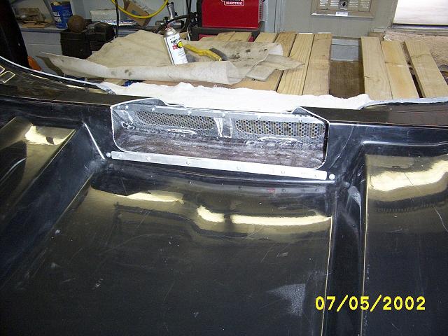
Air cleaner installed (temporatily) to check
for clearances. No, the stock hood will not fit. Not even close. Even a
3" Harwood cowl induction hood won't clear. It hit the aircleaner on the
back side where the hood reinforcement was. It also just barely touched the
front of the aircleaner (and it's a drop base air cleaner too!).. Looks like
it will take a 4" cowl to clear the aircleaner and that the back brace
of the hood will have to be clearanced/cut a little. Things to note:
Oh well…Lots more work to do….What a pain |
|
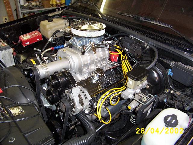
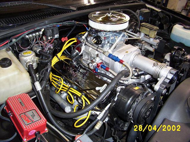
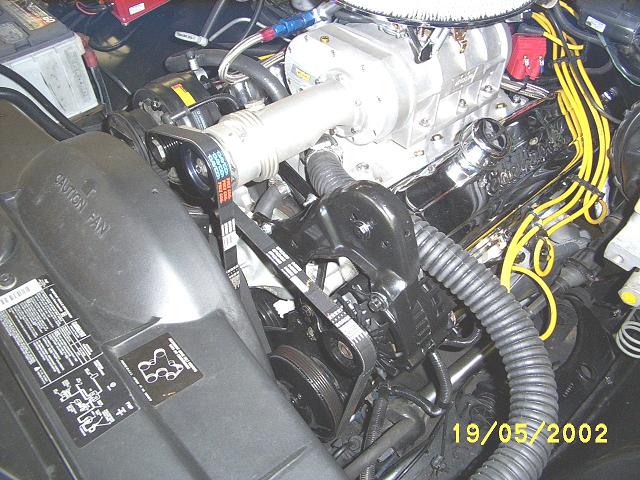
At this point the engine actually runs! This is the driver's side view of the completed engine. You can see the MSD Blaster SS ignition coil just behind the blower, mounted on the intake manifold. Under the coil, run the stainless steel braided fuel supply and return lines. The air cleaner is a 2" X 9" Weiand used for initial testing (I didn't want to burn up a good air cleaner if things went wrong J ) . The final air cleaner will be the Edelbrock 3" X 14". This picture does not show the final alternator bracket setup. I had to remove the serpentine belt tensioner and make the alternator position adjustable. The engine kept throwing the belt with this setup. For some reason, the tensioner made the belt run off track. In the final setup, I have the alternator mounted lower, and the radiator hose going above it instead of below it. |
|
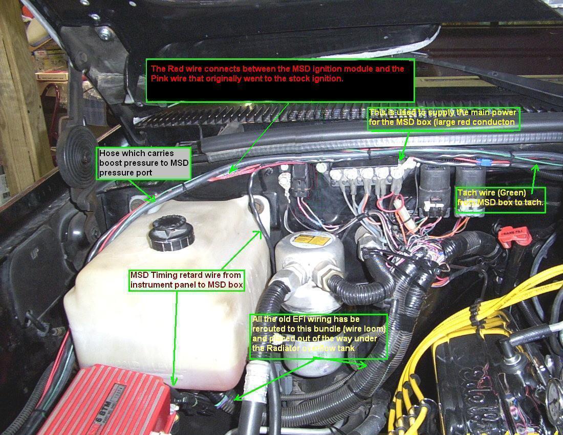
Can you find the ignition wires and controller
in this picture? The ignition wires are Crane Fire-Wire and
only cost me $10 including shipping. Crane was having a clearance sale and I
bought 3 sets of wires, for 3 different vehicles at $10 each. --what a deal! The MSD 6-BTM (Boost
Timing Master) ignition controller is the Red box in the left foreground of
the picture. The hose to the left of the MSD box is the hose that connects to
the boost guage and boost port on the back of the intake manifold. This is
used to boost reference the timing. The MSD Pro-Billet distributor is just barely visible in the back just behind the blower. |
|
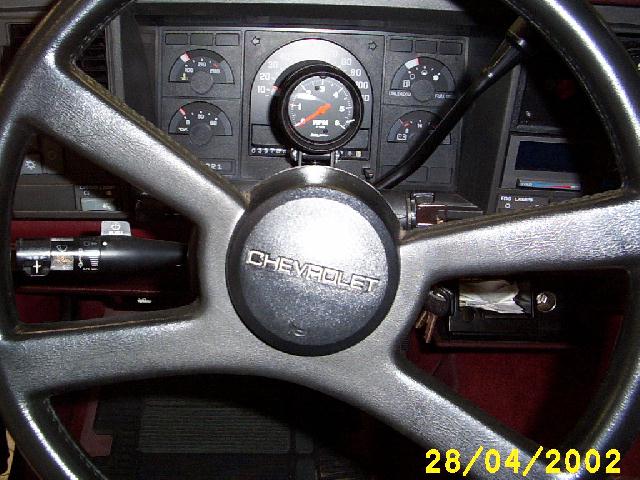
The tachometer is a 2-5/8" Autometer, 0-6000 Rpm, It is mounted on the bottom of the plastic instrument cluster frame on the hump over the steering column. I used an aluminum plate under the plastic as additional reinforcement. It doesn't show well on this picture, (because I was leaning into the truck when I took it) but the guage is centered just in front of the speedometer. |
|
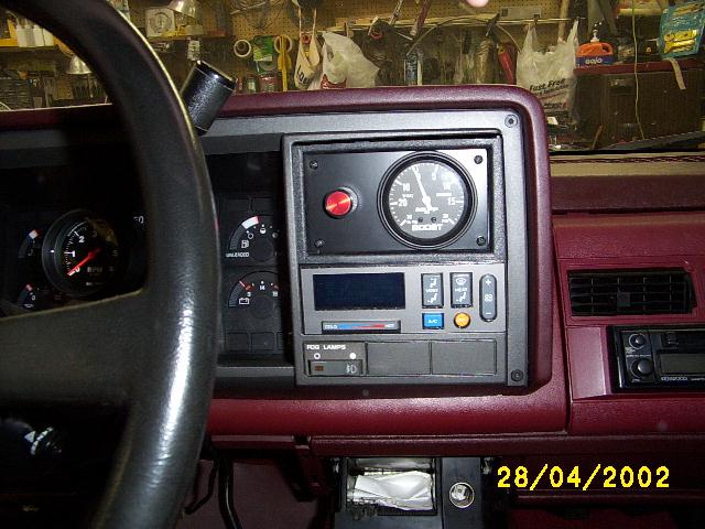
A picture of the 2-5/8" Autoguage Boost guage. The red knob to the left of the boost guage is the Boost Timing Retard control for the MSD 6BTM ignition controller. The Boost guage is mounted on a # 16 ga. Metal plate and the plate is attached to a "radio delete" box using aluminum L brackets . (The radio delete box is courtesy of Trevor Hitower of Mississippi) The panel is painted with Krylon semi-gloss enamel. |
|
|
|
|
|
Pic showing the mounting of the alternator and the radiator hose. |
|
Front view of the alternator mounting. |
|
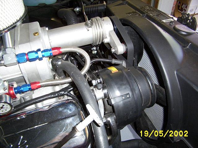
View of the A/C compressor mounting and the brackets which connect from the compressor back to the alternator. |
|
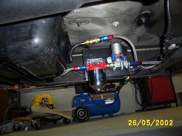
Fuel Pump. Final. |
|
|
|
|
|
|
|
|
|
|
|
|
|
|
|
|
|
|
|
|
|
|
|
HOOD WORK |
|
The hood had to be modified slightly to clear the blower. Note that I reinforced the cut out areas with aluminum bar stock on both sides of the cut. I used 1/8" X 1" flat aluminum bar stock and bolted them on each side of the fiberglass. The fiberglass edges are sandwiched between the pieces of aluminum. |
|
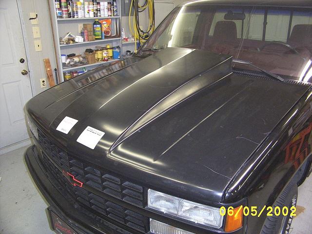
The 4" cowl induction hood installed on the truck. At this point it still has to be painted but at least it's on. It took quite a bit of cutting and grinding to make it fit. I am NOT impressed with Harwood quality (or lack of it). The hood latch was off by more than an inch. I had to move the stock latch forward and weld in a plate to mount it to, so it would line up with the Harwood hood. The secondary latch was also off center and a new one had to be fabricated. The Cervinis hood on the 91SS fit perfectly the first time. (unfortunately Cervinis did not make a hood with the 4" cowl). I do not recommend this hood as a simple bolt-on. Because it is not! Oh, and the scratches on the driver side occurred during shipping. Harwood packed it very poorly. Luckily nothing that the paint shop can't fix J |
|
the Harwood 4" cowl induction hood still needs painted, http://www.eharwood.com/products/db.cgi?uid=default&Category=Hoods&Make=Chevrolet&Model=Fullsize+Truck&Year=90&view_records=Search&nh=3&mh=1 The Harwood roll pan, on back order from
Summit was CANCELLED by Summit. Apparently the manufacturer is not currently
making this rollpan. Therefore the rear bumper will be reinstalled. |
|
Testing/tuning phase: Carb tuning… Early testing revealed a flat spot in the
3000-4000 rpm band and a hesitation/bog on rapid application of the throttle.
This was due to a lean condition. I rejetted the Holley 870 cfm vac secondary
carb to #82 on the primaries, and #88 on the secondaries. I also changed the
Accelerator Pump Nozzle (squirter/shooter) from #41 to #45. That cured the
flat spot and the hesitation. Ignition timing… Initially I had the distributor vacuum
advance line connected to the "ported" vacuum port on the carb, but
that was incorrect. That port has increasing vacuum with throttle…. Just the
opposite of what I needed. I then connected the vacuum advance to the manifold
vacuum at the base of the carb. That supplied the correct vacuum, but the
vacuum advance advanced the timing 15 degrees under full vacuum. Not good! So
I disconnected the vacuum advance and ran 13 degrees initial, and 24
mechanical for a total of 37 degrees of advance. The Boost Timing retard
control was set to retard timing 1 degree per pound of boost. (the blower
provided 5-6 pounds of boost) This seems to be the near optimum timing. Traction… Caltracs are a real pain to install. They
are practically useless with the stock Goodyear GT II radials. I have ZERO
traction with all the new HP/Torque. Hopefully, a set of BFG drag radials
coupled with the Caltracs will allow me to get some traction. Transmission…Things learned 1. When the vacuum line comes off the
vacuum modulator of the TH375/400 it will cause all kinds of weird
transmission behavior. Make sure you vacuum line is tightly connected to the
transission vacuum modulator. 2. The transmission would not shift out
of second gear under full throttle. This turned out to be a problem with the
computer still partly in control of the transmission. The solution turned out
to be to simply disconnect the transmission relay on the passenger side
firewall. The relay was holding the downshift in so that the trannmission
could not shift from 2nd to 3rd. 3. Also, the downshift detent no longer
works. This is also controlled by the computer. However it is not needed with
all the hp/torque now on tap. Fuel system… The fuel pump voltage is fed through
three possible routes. 1.
Through
the computers Hot fuel Handling Module. This supplies the fuel pump with
voltage for 20 seconds. 2.
Through
the computer. The computer must sense ignition pulses to supply this voltage.
(No pulses to sense with the carb conversion because I converted entirely to
an MSD ignition). 3.
The
oil pressure sender must sense oil pressure to supply voltage to the fuel
pump. -- guess which one I depended on and which one failed! The oil pressure
sender failed part way through testing. This caused the fuel pump the shut
off after 20 seconds. This only left fuel in the carb fuel bowls for the
truck to run on. This allowed the engine to run for about 1-2 minutes and
then mysteriously die. --a real pain to track down. I dug out the GM repair
manuals and tracked down the fuel pump wiring diagram. What a sorry wiring
diagram! Anyway, I replaced the oil pressure sender and discovered that it
was also reading high oil pressure. (In other words my oil pressure has been
running on the low side. Perhaps related to the blackened oil problem that
was showing up at every more frequent oil changes.) Oil pressure woes… During testing, the engine took a turn for the worse. While
making a few test runs, the oil pressure suddenly dropped to 1/2 normal.
Investigation revealed that the upper portion of the engine was not being
properly oiled. The oil was also blackened. The oil filter contained a
multitude of metal particles. Pulling the oil pan revealed that small amounts
of metal was in the oil pan. The oil pump was ok, but showed some signs of
the metal going through the gears. Alas, it was time to pull the engine. Off came the blower, accessories, and everything else just
installed. (The engine is HEAVY, and is a real pain to get unbolted from the
transmission.) Inspection of the bottom end (by Mitch James) revealed serious main and connecting rod bearing damage. It is suspected that this damage was caused by an incident the previous year when I had the oil cooler line break and I lost all the engine oil, starving the bearings of oil. Later it was discovered that the oil pressure sender was defective and was showing higher oil pressure than was actually present. Thus the line breaking and the oil pressure sender malfunction led to the oil starvation. The extra stress of the blower just accelerated the bearing damage that was already in progress. |
|
Begin Phase II. Blown 496 Stroker… Comp Cams NX 274H-13 cam Top quality bottom end: JE forged pistons, stroker crank,
rods, high flow oil pump. 2200 PTC stall converter. –Update: I installed this and hated it. It
felt like the tranny was slipping all the time. Shifts were very mushy.
I finally removed it and reinstalled the stock converter. Much better! Click on the Phase II and Phase III
links to view the rest of the story J $$$ |
Click here : for phase II, the 496 Stroker OR Click here : for phase III upgrades.