I'm building my modular synth using what I call a "function block" approach. This involves building small open-frame mounting platforms capable of accommodating 7-8 modules per block. Each function block has its own power supply and power cord, and they are small enough and light enough to be moved around as needed. The block contains a group of related or complemetary functions, so that many different patches can be accomplished with only a few blocks; the entire collection need not all be available (or even in the same room) all at once. Blocks can be moved around as needed, with parts of it performing different functions. Hence, the name "Discombobulator".
The current configuration of the Discombobulator, as of March 13, 2010, is:
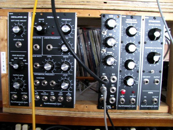
Left to right:

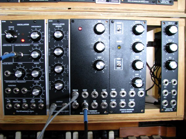
Left to right:
The MOTM-410 has a minor mod: the switch in the center of the panel disconnects filter 2 from the sweep input bus, so it can be driven by the internal LFO while an external signal drives the other two filters.
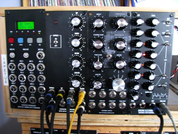
Left to right:
Left to right:
The CGS-57 has a mod: I installed a switch that alters the way that it scans through the switching capacitors. When the switch is down, then instead of scanning the eight caps in each bank in order, it scans them like this: 1-2-3-4, 1-2-3-4, 5-6-7-8, 5-6-7-8. It produces a different response curve from the filter.
Currently not installed: A Cynthia SterOSpace stereo expander, a Synthesizers.com Q128 A/B switch,a Cynthia/ Super Psycho LFO, a Cynthia Quad Lowpass Gate, and a STG Mankato Filter. The Super Psycho LFO is in the process of being rebuilt, due to an odd deterioration of the circuit board (all of the copper not covered by the solder mask is peeling off). This module didn't actually come from Cynthia; it was one of several partially completed ones that I bought used. The Quad Lowpass Gate came to me equipped with banana jacks, and I have not yet converted it. The Q128 is malfunctioning; the StereOSpace and the Mankato are working fine, but at the moment I don't have a space for them.
As you can see from the list above, I'm employing a Frankensynth approach. This gives me access to a huge cross-section of modules from several different brands. My theory on building mixed-brand modular synths is that many differences can be accommodated, but all modules must have two basic parameters in common:
For my modular, I have chosen to go with "large format" (also often referred to as "5U") modules. Currently there are three similar-but-not-identical individual formats in this category, referred to as "MOTM", "Dotcom", and "Modcan-A". All three of these formats follow a +15/-15/+5 power supply standard. For a current and complete list of 5U format modular makers, consult this list from Muff's Modules The manufacturers I have bought from or plan to buy from in the near future are:
| Company | Series | Format | How Sold |
| Synthesis Technology | MOTM 3-digit models | MOTM | Assembled, bare board & panel, partial kits |
| Synthesizers.com | Q series | Dotcom | Assembled |
| Modcan | A-series | Modcan-A | Assembled |
| Modcan | B-series | MOTM | Assembled |
| Cyndustries | Cynthia | Modcan-A | Assembled |
| Encore Electronics | MOTM | Assembled | |
| Bridechamber | MOTM and Dotcom | Assembled, bare board, panel (some modules), kits | |
| STG Soundlabs | Dotcom | Assembled | |
| Moon Modular | 500 series | Dotcom | Assembled |
There are two "small format" standards, the FracRack and the popular Eurorack standards. These have the advantage of taking up less space, but the tradeoff is smaller knobs and buttons (bad for those of us with fat fingers), and 1/8" or 3.5mm jacks, which are not as sturdy as 1/4" or banana jacks.
Mounting: Since these brands of modules differ somewhat in dimensions and mounting hole patterns, it is necessary to design the mounting rails to accommodate a variety of mounting positions. Rather than try to build a universal rack rail with multiple hole patterns, I chose to use undrilled wood rails. When building up or reconfiguring a function block, I position the modules where I want them, and then simply drill the rails wherever holes are needed. If, after several reconfigurations, a hole is in an inconvenient place (right next to where a new hole is needed, for instance), I simply plug it with wood filler and then re-drill.
Construction: The rails must have a specific distance between the top edge of the lower rail, and the bottom edge of the upper rail, in order for this to work. The lower limit on this distance is determined by the Dotcom modules, which have the panel sheetmetal sides bent backwards into "wings" which stiffen the panel; these wings must be able to fit in between the top and bottom rails. The upper limit is determined by the MOTM modules, which are slightly shorter than the other modules. The relevent dimensions are:
Now you see why the Dotcom wing height matters; you need to squeeze those rails as close together as possible to ensure that the screws won't breach the inside surface of the wooden rail when an MOTM module is mounted. I mount them so that the inside dimension is as close to the exact 7-5/8&qout; Dotcom wing separation as possible.
I build my function blocks on top of a plywood base, which serves as a mounting surface for the power supplies, power distribution, and any extension boards that I might want to add to a module. The plywood is 1/2" scrap material that I had left over from a major house repair job a few years ago. The rails consist of four pieces of 1x2 dimensional lumber. The frame is built with the narrow edges facing front and rear; the flat sides face up and down. They have an edge thickness of 3/4" which gives some extra thickness to accommodate the Modcan-A format modules, which are a bit taller (9") than the Dotcom/MOTM modules (8-3/4"). After some playing with the dimensions, I have settled on a basic platform width of 18-1/2" which gives me 8U or 9U worth of module width, depending on the combinations of modules used. The platform depth, front-to-rear, is 15" which provides plenty of room to mount the power supplies, distribution, and any auxiliary boards or circuits that need to be mounted but don't need to be on the front panel.
The bottom rail is glued directly to the platform with wood glue. The side rails stand on end on the platform, flush against the ends of the bottom rail (not on top of it). They are fastened via a flat-faced deck screw driven up through the bottom of the platform and into the end of the side piece; the screw is slightly countersunk so that the screw head won't snag on whatever surface the function block is set on top of. The top rail spans the tops of the side pieces, and is fastened similarly. When the whole construction is done, it is quite strong and I can pick up a fully loaded block by the top rail without damage. Recently, I have been adding tops to the modules, so that they can be stacked, and to keep foreign objects and dust from falling in. I add a 9" post at each rear corner, and cut a rectangle of 1/4" plywood for the top. This lays on the top rail and the rear posts, and is secured using Velcro, so that it can easily be removed for servicing.
There are no pre-drilled mounting holes. Whenever I am ready to mount a module, I drill holes where needed, and fasten the panel with wood screws. (For looks, I paint the heads of the screws with gloss black modeling paint.) When mounting an MOTM module, I drill at a bit of an angle, about 15 degrees, to ensure that the screw gets a good bite into the wood and doesn't punch through the surface. If I'm reconfiguring and a previous hole is in an inconvenient place, I fill it with wood putty.
Power distribution: I have experimented with two combinations of power supplies. For Titan, the first function block I built, I used a Condor dual-output linear for the +/-15 supplies, and a very inexpensive Phihong switcher for the +5. Rhea and Dione use Condor triple-output supplies that supply all three voltages. The triple-output linears cost more, are difficult to package because they are larger, and I'm not sure that there is any advantage. Conventional wisdon is that switching power supplies should be avoided in synthesizers (or any audio device) because they add noise to the circuitry. However, most modules that require +5 are generally using it for digital logic rather than audio circuits, and since digital logic is noisy anyway, any good designer will isolate these circuits from the audio. So, the advantage of using a linear for the +5 is negated. I've tried several of the Dotcom modules with both setups, and I haven't heard any difference. For Iepatus, I went back to using a switcher for the +5V, particularly since I intended this block to specifically accommodate the MOTM-650, which draws about 1/2 amp from the +5.
For power distribution, Titan, Rhea, and Dione use an MOTM-950 power distribution board. This board has 24 power connectors which MOTM modules will connect directly to, using the power cables supplied with each MOTM module. The MOTMs use a connector called the MTA-156, so called because the spacing between pins is 0.156". MTA connectors are available in widths of from 2 to 10 pins. The male connector mounts on the board, with its pins sticking straight up in a line. One one side of the line is a locking tab that engages a catch on the female connector. The female connector is mounted on the cable; wires are attached by pushing them into slots in the top of the connector. Female MTA connectors are particular about what gauge of wire is used; I've tried to use 18-gauge wire with connectors made for 20-gauge, and it doesn't hold together very well. The female connectors are color-coded as to what gauge of wire they are made to accept.
Most MOTM modules use a 4-pin MTA-156 connector. Holding the connector with the top up and the locking latches facing away from you, the pinout is (left to right): Pin 1: -15V Pin 2: return Pin 3: return Pin 4: +15V
Modcan uses a 3-pin MTA-156. With the connector in the orientation described above, the pinout is: Pin 1: return Pin 2: +15V Pin 3: -15V
Synthesizers.com uses a standard that is different in several respects. First, Dotcom modules require the +5V supply. Second, they use a more compact MTA-100 connector instead of the MTA-156. (As you have probably guessed, the MTA-100 connector has a pin-to-pin spacing of 0.100". This conforms with standard pin spacing for through-hole components, and so it is easier to accommodate in the circuit board design. It is also more compact and takes up less room on the board. The primary disadvantage is that the largest wire gauge that can be accommodated by a female MTA-100 connector is 22 gauge.
The pinout for the Synthesizers.com connector is: Pin 1: no connection Pin 2: -15V Pin 3: return Pin 4: +5V Pin 5: key Pin 6: +15V
The key pin, pin 5, is cut off from the male connector, providing a polarity protection feature. If desired, when fabricating a cable, pin 5 on the female connector can be plugged (using epoxy, RTV, or whatever is handy). This makes it impossible to plug the connector on backwards.
So how is the +5V distributed? On the blocks prior to Iapetus, I used a screw-type terminal strip. This type of strip has two rows of terminal screws. Each pair of screws is connected. I feed the +5 into one side and use jumpers to pass it along to all of the other terminal screws on that side. When I need to connect a module that requires +5, I connect the +5 wire to the terminal strip individually after pluggin its connector into the distribution board.
Starting with the Iapetus block, I have switched to using the MOTM-990 distribution board. This board distributes all three voltages and has ten 6-pin MTA-156 connectors, corresponding to the newer MOTM standard for digital modules. This new standard provides for +5 and also separates the analog and digital grounds. The MOTM-990 also has six of the older-style 4-pin connectors. This way, I can make a cable that connects to the 6-pin connectors for the Dotcom modules, and I don't have to have the separate terminal strip to distribute the +5.
Fabricating female MTA connectors: Wires are attached
to the connector by shoving them down into the slot
on top of the connector, and into the crimping blades
of the contact. It is not necessary to strip the
wire first; the crimping blades will cut through it
to make contact with the conductor. In fact, the
connection holds better if the wire is not stripped.
If you have looked up
the MTA connectors in the Mouser catalog, you have
probably been horrified by the cost of the crimping
tool. If one were to buy the crimping tool itself
plus the two heads required to crimp both MTA-156
and MTA-100 connectors, the cost would be well over
$400 U.S. At this point I have a confession to make:
since the last time this page was updated, I splurged
and got the crimping tool and heads. I just wasn't getting
consistently good results with the maintenance tools.
However, if you are still interested in saving some
money and you have more patience than I do, here are
the details on the maintenance tools:
There is a maintenance tool for each of the two
sizes, for about $25 apiece. These are nothing more
than a plastic T-handle with a serrated blade at the
end. Here are the Mouser
stock numbers for the maintenance tools:
With a bit of practice, you can do without even the maintenance tools. A small flat-bladed screwdriver will do. You need one with a width slightly smaller than the gauge of the wire, about the width of a small knife. Either of these two methods will work fine for low-volume production.
Insert the wire into the top of the connector, holding the wire horizontally (in other words, don't stick the end of the wire down into the contact; lay it across). Shove the wire down in with the tool or the screwdriver. Don't strip it first; the connector bites through the insulation, and it holds better if the insulation remains on. One thing you cannot do is use the wrong gauge of wire. The connectors come color coded to show what gauges of wire they take. If you are mixing MTA-100 and MTA-156 on one cable, pay careful attention to this; there is only a narrow range of wire gauges that are available for both types.
One other area to address is that of signal interconnects. I have standardized on 1/4" jacks, also known as "phone" jacks, for all of my patch cords and interconnects. The MOTM and Dotcom format modules all use 1/4", so no problem there. However, the Modcan-A format modules use banana jacks. THe problem here is that banana jack patch cords are single-conductor cords; they rely on the power supply return and/or the mounting frame to be the signal return path between modules that are connected together by a patch cord. My wood mounting frames don't provide a conductive path between modules, and relying on the power supply returns for signal paths is not ideal from a noise standpoint. Dotcom sells an interface module that interconnects banana-jack and 1/4" modules, but it requires that the banana jack modules have a back-of-panel ground connection to the interface module, and then it is still necessary to have two types of patch cords in inventory.
I have chosen instead to convert the Modcan-A modules that I currently own to 1/4" format. Cyndustries has given me their blessing to do the conversions on their modules, and they have helped by selling me various piece parts that I needed. The steps involved are: drilling out the jack holes to accommodate the 1/4" jacks (which are somewhat larger than the banana jacks), and finding a good grounding point to connect the ring terminals of the jacks to. A problem that can occur is that, if clearances around the jacks are close, there may not be enough room to mount the 1/4" jacks. I currently have that dilemma with a Low Pass Gate module that I have, and I haven't figured out yet what to do about it. Here is a photograph of a Steiner Filter module conversion:
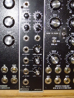
This one was relatively straightforward, as there were no close tolerances around the jacks, and the board (the module is based on a board from CGS) had a readily available signal ground point.